tributed loaded and supported along its perimeter,and the rquirements of the serviceability limit sa shall be saisfied simultaneouy. 5.3.3 For the uniformly distributed loaded slab-column system,according to the distinguishing features layout and loading,that the design values of intemal fores for ultimate limit states can be calculated using the coefficient of bending moment method or the equivalent-frame method etc. 5.3.4 The most important or the special stressed states large-sized rod series structures,as well as the two-dimensional and three-dimensional structures,the non-linear analysis under whole process of stressed states for the integral stuctures or parts of structures shall be. The non-linear analysis of structures may confom to the following principles: 1 Shapes,dimensions and boundary conditions of structures,as well as the grade of strength for materials and the amount of principal steel reinforcements shall be pre-determined; 2 The mean values shall be adopted for the indexes for properties of materials; 3 The non-linear constitutive relation for materials,sections,members or various computing units may be determined by experimental results;or by verified mathematical model,its parameter vacorvithi basis.Thenothe multiaxial strength and the failure criterion of concrete,may be adopted according to Appendix C; 4 The disadvantageous influences for the geometric non-linearity of structure on the action- effects,may be counted; 5 The fundamental combination of action-effects shall be taken on the limit states and the corresponding correction shall be made in accordance with the distinguishing fea- tures of states and the failure mode of structural members;and the characteristic combination and quasi-permanent combination of action-effects may be adopted for the checking calculation of the serviceability limit states. 5.3.5 The serviceability limit states and ultimate limit states of structures or parts of structures, which are in complicated shapes or under special stressed states,shall be analyzed or checked respec- tively by methods. 5.3.6 A specialized structural analysis shall be performed,when the temperature and the humidity where,and the the structure the factors of shrinkage and creep ctc.in concrte may be possible to harm the safety of structures or the service- ability of structures. 24
6 Requirements for Calculation of Prestressed Concrete Structural Members 6.1 General Stipulations 6.1.1 In addition to the calculation of load-bearing capacity and the checking calculation of deformation,crack-resistant,crack width and stress,according to the conditions of usage, prestressed concrete structural members shall still be checking calculated in accordance with different actual construction stages,such as fabricating,transporting,and erecting,etc. The design value of prestress is given by calculation equation in relevant Chapters of the code,when it is considered as load-effects.For ultimate limit states,the partial safety factor for prestress of 1.0shall be taken when prestress-efect is advantageous to structures;or disad- vantageous to structures,the partial safety factor 1.2 shall be taken.while the partial safety factor for prestress of 1.0 may be taken for serviceability limit states. 6.1.2 When membens are sufficient to meet requirements for crack control by applying prestressed fors in part of longitudinal steel reinforements,hence the nor-prestressed steel reinforements may be used for the rest longitudinal steel reinforcements,which need steel to meet the calculated load- bearing capacity of members.The steel bars of Grade HRB400,Grade HRB335r Grade RRB400 may be adopted for non-prestressed steel reinforcements. 6.1.3 The value of stretching not ex the allowable value of contolled stress for stretching as stipulated in the Table 6.1.3,and shall be not less than 0.4/a. When there conforms to one of the following conditions,the allowable value of controlled stress for stretching in the Table 6.1.3.may be increased by.05 1 In order to increase the crack resistance in the construction stage for the members,it is re- 2 It is required to offset a part of the loss of prestress caused by the factors of stress relaxation, friction,batch stretching of steel reinforcements or the difference of temperature between the pre stressed reinforcement and the stretching bed etc. Table 6.1.3 Allowable Vahe of Comtrolled Stress for Stretching Method of stretching Pre-tensioned Post-tensioned Sess-relief steel wire,srand 0.75f4 0.75jA Heat-treated steel bar 0.70fd 0.65ja 6.1.4 When a member is to be prestressed,the compressive strength of concrete cube shall be deter- mined by calculation,but may not be less than 75%of the designed concrete strength grade 25
6.1.5 The nommal stress in concrete and the stress of prestressed steel reinforcement at corresponding stages,whicharecsd by prestressing force,may be calculated respectively accordingto the follow 1 Pre-tensioned members (6.1.5-1) Ope =doon -dI-agdpe (6.1.5-2) Stress in prestressed steel reinforcement when the normal stress in concrete is equal toero at the point ofof foresfor p0=dcan -01 (6.1.5-3) 2 Post-tensioned members Normal stress in concrete caused by prestressing forces: (6.1.5-4) Effective prestress in the prestressed steel reinforement at coesponding stage Ope dcon -d1 (6.1.5-5) Stress in prestressed steel reinforcement when the nommal stress in is equal to ero at the point of resultant of forces for prestressed steel reinforcements 0do=dcon OI QEOne (6.1.5-6) Where A。 total areas of concrete excepted from the weakening parts such as openings,concaves etc.,and the transformed sectional areas of concrete from all the sectional areas of longitudinal non-prestressed steel reinforements;for sction composed of concrete with different stength grades,the sectional area shall be transformed in to the sam grade,crding to the ratio of the elastic modulus of crete: :including the net the transformeds the of longitudinal forcements; momentof inertia for transfommed secton,moment of inertia for net section respective ep、epm -distances from the centroid of transformed secuon,the centroid of net secton to the point of resutant oforsfor presressd rinformentand nonprestressdrinfor ments,respectively,acrding to the stipulations in the Clause6.1.6of the code; Y0yn -distances from the centroid of transformed section,the cenid of net 公
culated fiber respectively; the value for loss of prestress at cosponding stnge,calculated according to the stipulations in the Clauses 6.2.1 to 6.2.7 of the code; iof modulus of elasticity for to modulus of ofco crete:ag=E/E,where E,is taken from the value listed in the Table 4.2.4 of the code and E may be taken from the value listed in the Table 4.1.5 of the code; No Np esuan of forces for prestressed and nonprestressed steel reinforements in pre-ten sond member,post-tensioned member respestively calcutaled according tothe stipu- lations in the Clause 6.1.6 of the code; M2sub-bending moment which is produced by prestressing force Np in the post-tensioned prestressed concrete statically indeterminate structure,calculated according to the stipulations in the Clause 6.1.7 of the code. be adoped when the directions are opposite;equations(6.1.5-2)and (6.1,5-6)are suitable for the codtonsr the cmpesivehnis the tensiletreve value shall be taken; the restricting members suc the coumn and the wall elc.on the prestressing effect of the beam and the slab. 6.1.6 The for and steel reinforcements and theeccen tricity of the point of resultant of forces(Fig.6.1.6)may be calculated by the following equations: 1 Pre-tensioned members No=OpAp+op Ap -aisA.-ois A: (6.1.6-1) e0=©An的45-sAx+6A (6.1.6-2) OpoAp+Ap -aisA.-ais A: 2 Post-tensioned members Np=OpeAp+ape Ap aisA.-ais A: (6.1.6-3) n-e4m45。-sA,y-贴A (6.1.64) OpeAp+ope Ap OisA.-ais A: Whereinpff the com,the tension zone respectively,when the normal stress in concrete,at the point of resultant effective prestress in prestressed steel reinforcements of the compressionoe, the tension zone respectively; zone,the tension zone respectively; A.A one,the tension zone rspectively; 3
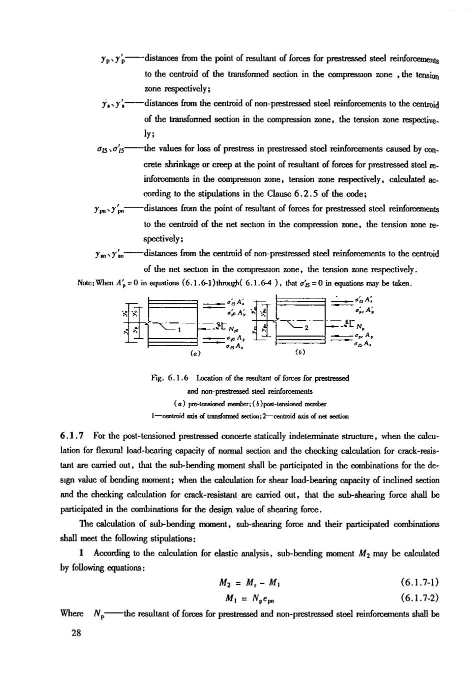
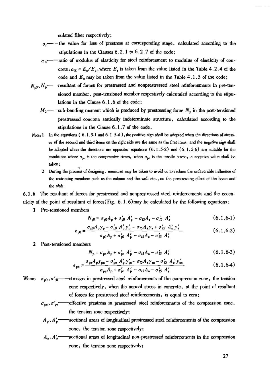
distances from the point of retan of forcesfor prestressed steel reinforceme to the centroid of the transfomed section in the compression zone,the tension one respectively ydistances from the centroid of non-prestressed steel reinforcements to the centoid of the transfommed section in the compression one,the tension zone respective- ly: -the values for loss of prestress in prestressed steel reinforcements caused by con crete shrinkage or creep at the point of rsutant of forces for prestressed steelre ,respectively, cording to the stipulations in the Clause 6.2.5 of the code; to the centroid of the net secon in the compression oe,the tension one re spectively; from the centroid of non-prestressed steel reinforcements to the centroid of the net section in the compression zone,the tension zone respectively. Note:When=0in tions(6.1.6-1)through(6.1.64),that=in may be taken (a) 6) Fig.6.1.6 Location of the ruan of fores for prestred andnonprestresedstedeinoreements ()pre-d l-eatoiduddtmdamadseoetiani2-cemtoidadiacdndocdioca 6.1.7 For the post-tensiond prestressed statically indeterminate structure,when the calcu lation for flexural load-bearing capacity of normal section and the checking calculation for crack-resis- ou,that the sub-bending moment shall be participated in for the de sign value of bending moment;when the calculation for shear load-bearing capacity of inclined section and the checking calculation for crack-stant are out,that the subshearing force shall be participated in the combinations for the design value of shearingfore. The calculation of sub-bending moment,sub-shearing force and their participated combinations shall meet the following stipulations: 1 According to the calculation for elastic analysis,sub-bending moment M2 may be calculated by following quations: M2 =M,-M (6.1.7-1) M1=NpCpn (6.1.7-2) Where Nthe fores for prestressed and no-prestressed stee shall be 动