calculated according to the equation(6.1.6-3)of the code; -the distance from the centroid of net section to the point of resuant of forces for pre stressd and non-pressdsteel shall equation (6.1.6-4)of the code; Mthe value of bending moment from the of prestressing force Nto M,-the value of bending moment resulting from the equivalent load of prestressing force Ne on the section of structural members; The subshearing force may be calculated by structurl mechanics method according to the distri- bution of sub-bending moment in the varied sections of members. 2 When the calculation of flexural and shear load-bearing capacity for sections are carried on, where the participated sub-bending moment or the sub-shearing force in the combinations is disadvanta- geous to structure,that the partial safety factor of presess 1.2 shall be taken;while the 1.0 shall be 3 When the checking calculations of crack-resistant in flexural and shear for sections are carried on,that the partial safety factor of prestress 1.0for the sub-bending moment and the sub-shearing force in the combinations shall be taken. 6.1.8 For the posi-tensiond girder and continous beam,undr the con ditions meet the requirements of minimum ratio of reinforcement for stressed steel bars specified in the the code,when the relative height a.3,that there distribution of intemal forces can be considered,and the 10%amplitude modulation of bending mo- ment can be usd for the sction of support,as wells,the requirments of checking calcutation fo the serviceability limit states shall be met too;whene>0.3,the redistribution of interal forces may not be considered.Hence,theshall be calculated according to the stipulation in the Chapter7of the code 6.1.9 The prestressing transmission lengthof prestressed steel reinforcement for pre-tensioned lu a (6.1.9) Wherethe effective prestress of prestressed steel reinforcement when relaxed stretching; Appendix B of the code; -the appearance coefficient of prestressed steel reinforement shall be adopted accord ing to stipulated in the Table 9.3.1 of the code; fcharacteristic value of axial tensile strength coeponding to compressive strength of concrete cubefduring relaxed stretching,which is determined using linear interpo- lation methods specified in the Table 4.1.3 of the code When hection proofuddeny reaxed for the prstresdsteereinforcement is adop- 29
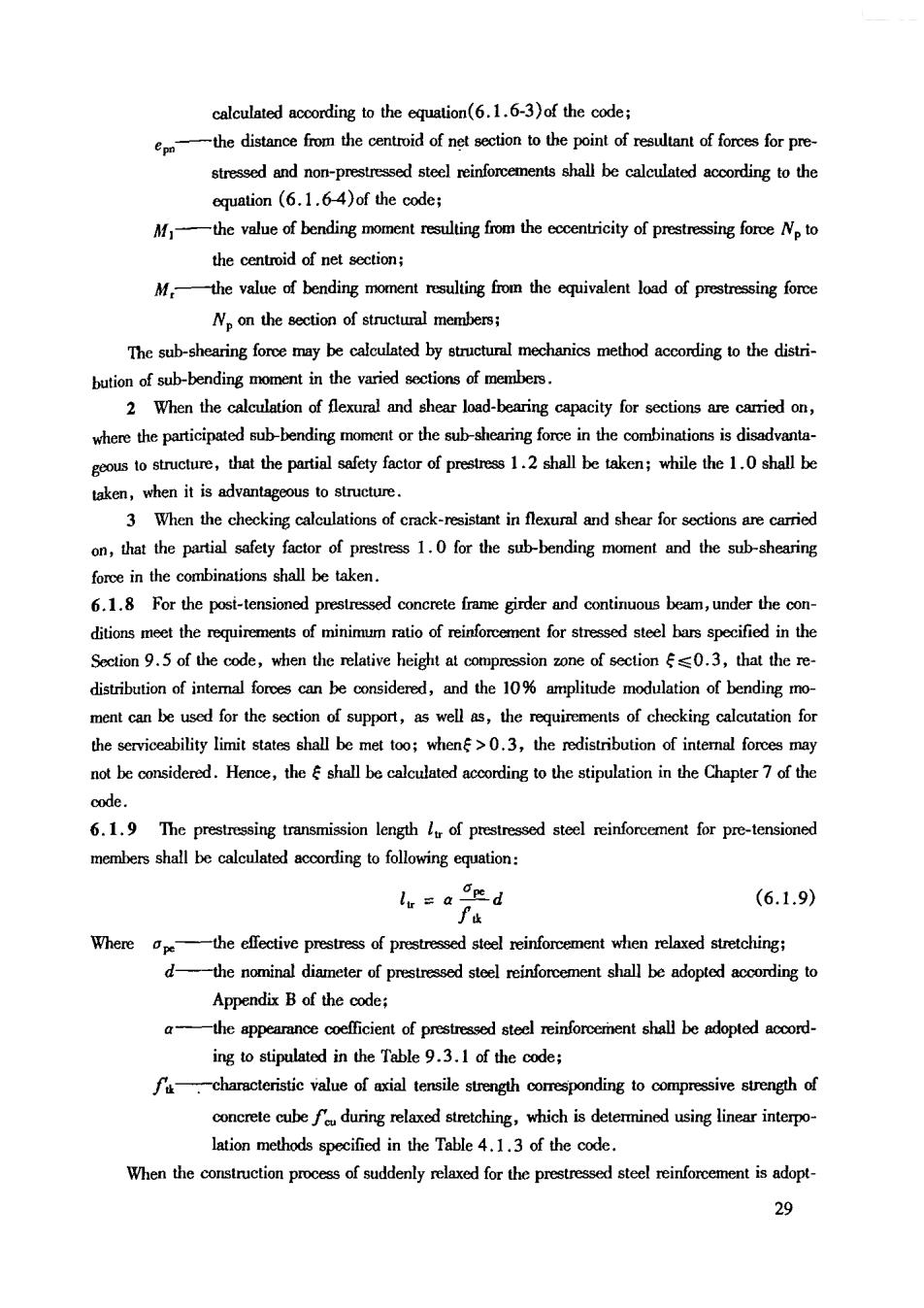
ed that the startng point for calculation of shall be0.25 from the end of member. 6.1.10 When in calculation of the nomal sectional or inclined sectional flexural load-bearing capaci- ty at end anchorage zone of pre-tensioned prestressed concrete member,within the range of anchorage length,that the design value of tensile strength for prestressed steel reinforcements shall the starting point of anchorage,and at the end point of anchorage shall takeffor the values between these two points can be determined by linear interpolation.The anchorage length of prestressed stee reinforcements shall be determined according to the Clause 9.3.1 of the code. 6.1.11 In addition to the checking of utimae limit states at the stagefor prestressed concrete structural members,the members in which crack is not allowed in the pre-tension- at the extreme fiber of concrete under the actions of prestressing force,self-weight and construction load (dyamic shall be,if comply with the following stipulations ig.6.1.11): ta) ) Fig.6.1.11 Checking members at construction stage (a)pre-tensioned member;()post-tensioned member; 1-centroidaisoftrnnsfomedsection;2-centroidaisofntscetion oc≤fk (6.1.11-1) 0e≤0.8f6 (6.1.11-2) The nomal of conrete at the xtreme fiber of section may be calculated by the following equation: (6.1.11-3) Wherethe compressive stress,the tensile stress at concrete the extreme fiber of calculat respectively fua- characteristic values of tensile stength,compressive strength respectively,corre- sponding to the compressive strength of concrete cube in each consruction-stage they may be determined by linear interpolation method acording tothe Table 4.1.3 of the code; Ni,My- duced by the characteristicmntioofcio load and sefweight of the member; Wo- elastic resisting moment of transfommed section,at checking calculated extreme 30
fiber. stressing force: (6.1.11-3)positive vale;hn s te te silesestaking negative value;when Mis the aia compressive force,taking positive value;hen M istheoe,taking ngtivevalue;henreme fierd byMiscomrssv cnntion 6.1.12 In addition to the checking of utimate limit stage of pre sressd oete structural members,for members on which cracks are allowed and longitudinal pre treme fiber shall of to following stipulations: oc:≤2fh (6.1.12-1) cx≤0.8f (6.1.12-2) Herein theshall still be calculated according to the stipulation in the Clause 6.1.11 of the code. 6.1.13 The reinforcement of longitudinal steel bars in pretenson one of prestressed concrete struc tura member shallnto the followingqremens: 1 For members in which cracks in the pretension one is not allowed during the constructon stage,the ratio of reinforcement for longitudinal steel bars in the pretension(AAA shall not be less than 0.2%,while A shall not be counted for post-tensioned members,where A is the 2 For members where cracks'in the pretension zone is allowed during the construction stages, and longitudinal prestressing steel barsare not provided in the pretension one,when= ratio of reinforcement for longitudinal steel bars in the pretension zone AA shall not be less than 0.4%;whenff,it may be dctennined by linear interpolation method between 0.2% and0.4%: 3 The diameter of longitudinal nonprestressing steel bars in the pretension zone may not be greater than 14 mm,and shall be provided uniformly aong the outer edge of the pretension of the member. nfomfor longitudinal steel bars in the pretenson may be determined byrce inrdace with actual conditions of the member. 6.1.14 In the calculation of load-bearing capacity and crack width for pre-tensioned and post-ten sioned prestressed conrete members,when the norma prestress in concrete is equal to,the resul- tant of forces for prestressed and nonprestressed steel bars No and the eccentricityo for the come- sponding point of of fores,shall be calculated according to the equations(6.1.6-1)and (6.1.6-2)of the code.The stresses of prestressing sreel bars in pre-tensioned and post-tensioned 31

6.2 Calculation of Values for Loss of Prestress 6.2.1 The valucs for oss of prestress in prestressed be calculated to the stipulations in the Table 6.2.1. Table 6.2.1 Vabues for Loss of Prestress(N/mm) Factors lead ls Symbols Pre-tensioned Post-tensioned member Defomation of anchoge at streching Calculated according to the stinulation in the to the stirulation in Clause 6 2.2 and Clause the Clause 6.2.of the c 6.2.3 of the code Calculateding Friction with to the stipulation Friction of duct wall in the Clause 6.. of the code atee】reinforcement Friction at Detemined actunlsiuatior unit location At the time of heat the temp 2At stretched steel reirforcemert and 8 General relaxation: 0.4(-0.5j where,Once sreiching=1 Excessive stretching=0.9 Lowrextion: lit cn≤0.7yt steel reinforcement 0.12(-0 hen0.ja<om≤0.8t 0.22-057e Heat treated se bar Once stretching 0.05d 名
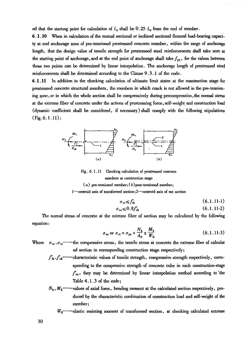
(continued) Pre-tensioned Post-tensiond Factorseadto Calculated according to the stipulation in the Clause 6.2.5 Shrinkage and creep of concrete of the code prestresdsenforwhen the diameter dm,resultingfrom 西 sretched sterenftand tensined quipen 2 The procedure of excessive stretching given in this Table start fromestres1.03or fromr tneslo1.0sgom,ierholdirgeladfa2ninais,nloedingodce en as zero. When the calculated total value for loss of prestress is less than the following values,the values as follows shall be adopted: Pre-tensioned members 100 N/mm Post-tensioned members 80 N/mm2 6.2.2 The value for loss of prestressed straight steel reinforcement due to the deformation of anchorage and the inner shortening of steel reinforement may be calculated by the fol- lowing equation: %=“E, (6.2.2) Where a- steel reinforcement (mm)may be taken as the value listed in Table 6.2.2; -distance from the stretching end to the anchored end(mm). Table6.2.2 VailesfrDfomaiaodAndihorgeadlmersherteing of Steel Reinforcement a(mm) Type of anchorage a Seam of mut Supporting type anchorge (Button-head anchorage for ste wire bunde etc.) Seam of each post-dding shi 5 ping picce typecrg 5 Without top pressure6-8 of steel reinfom nent in the Table 2 For oher types of anchrge,the values for the defommation of nrage nd thenershortening of steel