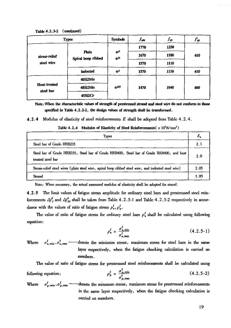
Table 4.2.3-2 (continued) Types Symbols ∫a fg 170 1250 Plain stress-relief Spiral boop ribbed 1670 1180 中H o steel wire 1570 110 idented 1570 1110 410 40Si2Mn 48S2M恤 1470 1040 400 45S2C sed strnd d stee wire do specified in Table 4.2.2-2.the design values of strength shall be trar 4.2.4 Modulus of elasticity of steel reinforcements E shall be adopted from Table 4.2.4. Table 4.2.4 Modulus of Flasticity of Steel Reinforcements(xN/mm) Types E。 Stcel bar of Grade HRB235 2.1 Steel bar of Grade HRB335.Seel bar of Grade HRB400,Steel bar of Grade RRB400,and heat trealed steel bar 2.0 te wres (plain ire,piral hop ribbed and indentede wire) 2.05 1.5 4.2.5 The limit values of fatigue stress amplitude for ordinary steel bars and prestressed steel rein forcements Aff and fy shall be taken from Table 4.2.5-1 and Table 4.2.5-2 respectively in accor- dance with the values of rtio of fatigue stress The value of ratio of fatigue stress for ordinary steel bars p shall be calculated using following (4.2.5-1) Where af.minas,mux -denote the minimuim stress,maximum stress for steel bars in the same layer respectively,when the fatigue checking calculation is members. The value of ratio of fatigue stress for stee shall be calculated usng following cquation: (4.2.5-2) Where ap.minap.ma -denote the minmum stress,maximum stress for prestressed reinforcements in the sme layer repectively,when the fatigue checking carried on members】 9
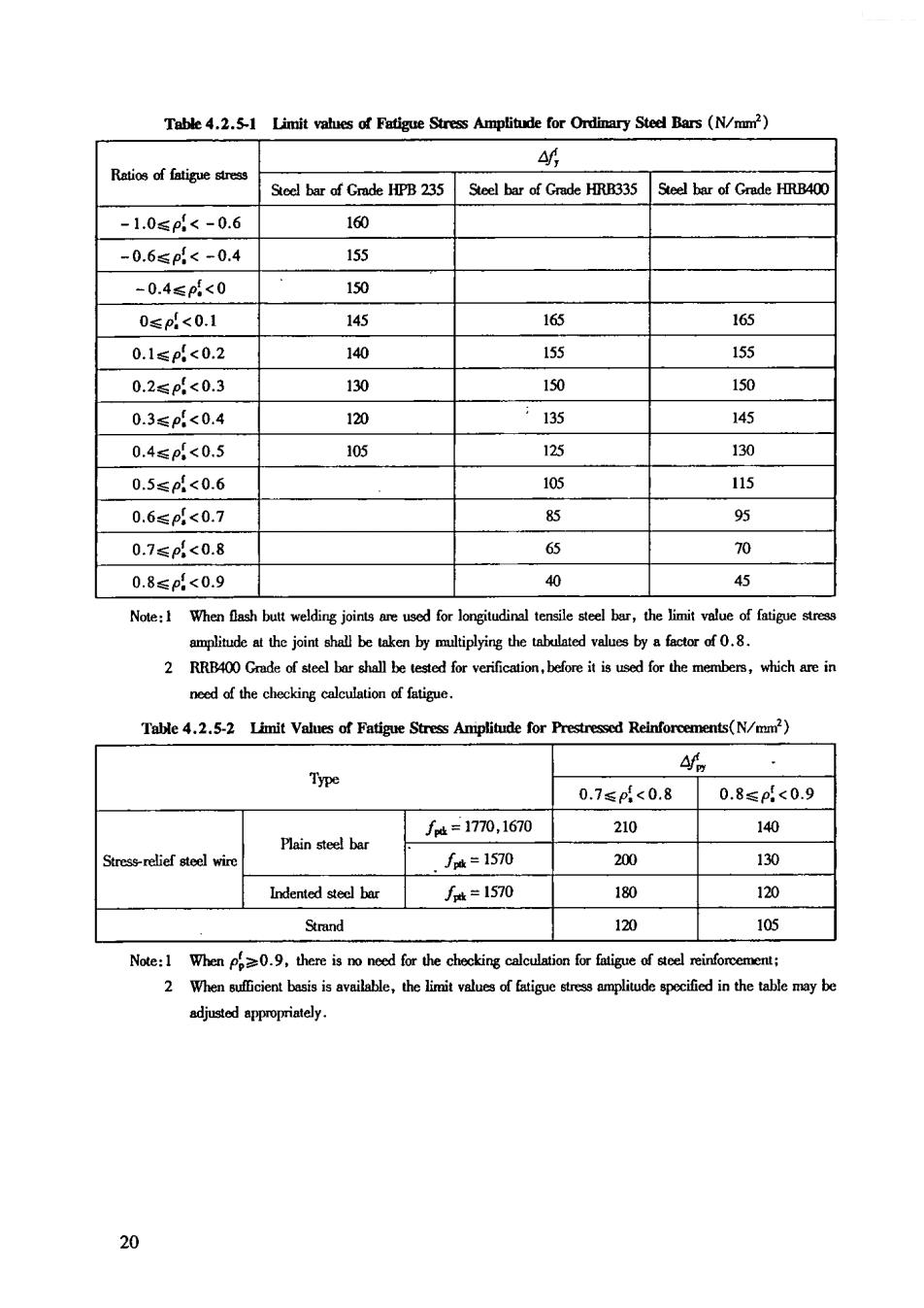
Table 4.2.5-1 Limit vahues of Fatigue Stress Amplitude for Ordinary Sted Bars (N/mm) Ratio of fatigue Seel bar of Gmde HPB 235 Steel bar of Gmde HRR335 Steel bar of Grade HRB400 -1.0≤p4<-0.6 160 -0.6≤p<-0.4 155 -0.4≤p<0 150 0≤pd<0.1 145 l66 165 0.1≤p<0.2 140 l55 155 0.2≤p<0.3 130 150 150 0.3≤p<0.4 120 135 145 0.4≤p<0.5 105 125 130 0.5≤p<0.6 115 0.6≤p<0.7 85 95 0.7≤p<0.8 6 70 0.8≤p<0.9 40 45 Note:1 When ash butt for longitudinal bar,the limit value of fatige 2 RRB400 Gnade of stee bar shall be tested for verificalion,before it is used for the members,which are in need of the checkine calculation of fatimue Tae 4.2.5-2 Limit Values of Fatigue Stress Amplitude for Reinforcements(N/ 4 Type 0.7≤<0.8 0.8≤p.<0.9 f4=1770,1670 210 140 Plain steel!bar ,/k=1570 200 130 J∫#=1570 180 120 120 105 is o ed for the checking c or fatigue ofe 2 When sficient basis is available,the limit values of specificd in the tabe may be 9
5 Structural Analysis 5.1 Fundamental Principles 5.1.1 In the calculation of the ultimite limit states and the checking calculation of serviceability limit states,the analysis of action(load)effects for structural integrity shall be carried out in accordance with the actons (loads)specified in national current relevant standards;when necessary,a more de- tailed structural analysis shall be carried on the special stressed parts of structures. 5.1.2 When there are various stress situation in the structure at the stages of construction and appli cation,the structural analysis shall be performed respectively,so as to determine the most disadvanta- geous of action efc. When there are possibilities for structures in meeting accidental actions,eg.fire,explosion, strike etc.,the structural analysis shall be carried on respectively in accordance with reqrements specified in national relevant current standards. 5.1.3 When performing structural analysis,all dimensions,used computing graphs boundary conditions,effective value and combination of actions,computing indexes for material prop- ry,initial stress and state of deformation tothe actua orking sitation of tures,and the appropriate guarantee measures for structural detailing requirements shall be taken. Alsinmpliiedandappoxinalessunmptionsueodinstnuoturnlanalysisshlbesuponadbytheo ries or experiments,or be verified by engincering practices.The accuracy of results of computation 5.1.4 Structural analysis shall meet following requrements: 1 Shall stisfy the cquilibrium condition of mechanics; 2 Shall confomm to the coordinated condition of deformation in varying degrees,including re int conditions of the ndal point and the boundary. 3 Shall adopt the reasonable constitutive relation for materials or unit of member. 5.1.5 When performing structural analysis,the following methods shall be taken according to type of ,layout of members,property of materials and features of.: Linear elastic analysis method; -Considering the plastic redistribution of method; -Plastic limit analysis method: -Non-linear analysis method; -Experimental analysis method. 5.1.6 The cmputer aided design program,which is used in structural analysis,shall be checked and verificd,and its technical conditions shall meet the rqurements of this code and relevant stan- dards The results of computer aid design shall be judged and checked,it can be used for design of en- 21
gineenng until they are affimmed as reasonable and valid. 5.2 Linear Elastic Analysis Method 5.2.1 The linear elastic analysis method may be used in the analysis of action-ffects of utimate limit states and serviceability limit states for concrete structures. 5.2.2 Integral structural analysis may be performed for the rod series structures according to the space system,and the influence of the deformotions due to flexural,axial,shearing and torsional on structural intemal forces may be considered. 1 The space rod series structures in regular built form,which can be divided along the column the space coordinative works of these plane structures may be taken into account; 2 When the influences n structural intemal forces resulting from the axial,shearing and tor sional deformations of rod member are slightly,it may be neglected; 3 When the infencesnscond-order effects of intemal forces sulting from the deformations of structures or rod members are slightly,it may be neglected. 5.2.3 The computing graph ofd series structures may be determined acordingtofollowing meth- ods: 1 The connecting line situated in geometrical center of section may be taken as the axial line of 2 The nodal point of beam-column and the connection part of column and foundation,ctc.in the cast-in-situstructure and in the assembled monolithic,can be regarded as rigid joint;the beams,slabs with supporting members,which are not cast-in-situ,can be regarded as hinge joint; ter to center distance or clear distance of the length between two supporting ends,and may be corrected according to the oting rigidity of supporing joints,or the positions of supporng reactions; 4 When the rigidity of the connecting part between d membes is far greater than that of the middle sction ofrod members,it can be regarded as a rigid domain inserting into the computing 5.2.4 The rigidity of section for rod member in rod senes structure shall be detemmined according to following methods: 1 The elastic modulus of concrete shall be adopted as specified in the Table 4.1.5.of the code; 2 The sectional moment of inertia can be calculated in accordance with the full section of uni fomly graded conret 3 The mmen of inertial of T-shaped sc member may be calcuad based on the effective width of flange,or may be determined after coction on the momentof inertia for the area of part of 4 For the end haunched member,the indluence on the structural analysis resulting from the 22
changes of rigidity shall be considered; 5 The rigidity of member under different stressed states,may be decreased appropn- ately for the consideration of influence from factors for the crack and the creep of concrete etc. 5.2.5 The analytical methods including the interpretative methd,the finite-element method or th finite-difference method ete.,may be adopted for rod series structures.For the regular built form struc- tres,the effective simplified anaytical method may be adopted dependingon the distinguishing fea tures of stressed states and the type of actions. 5.2.6 For the end of beam,which is integrally casting with supporung members,can be designed using the values of intemal forces on extreme fiber of section at the support or the nodal point. 5.2.7 In the of limit states and the checking calcutalion of erviceadility limi states for various two-way slabs,that the linear elastic methods can be used for the anlysis of action- 5.2.8 The elastic theory analysis,the finite element analysis or the experimental method can be used for with two-dimensionar three-dimensional structures to determine the distribution of elastic stresses,the required amount and the layout of steel reinforcements are determined in accor- dance with thearea of principal tensile stresses graph,and of checking ca lated by the multi-axial stress states.The multi-axial strength and the failure criterion of concrete can When the structures in calculation of ultimate limit states,the design values of actions and the in- dexes of properties of materials can be taken;when the structures in checking of ability limit states,the characteristic values of actions and the indexes of properties of materials can be taken 5.3 Other Methods for Analysis 5.3.1 The plastic redistribution of stresses amalysis method may be used for the reinforced concrete continuous beams and on-way sls,that the values of intemal forces can be detemmined by the method of amplitude modulation for bending moment. For frame,frame-structural (shear)wall structures and two-way slabs etc.,after the intemal forces have been obtained through the elastic analysis,that the amplitade modulation can beasca ridonthe bendingmn of the supporrnda point,and to determine thesponding bending moment at midspan Sructures and members desined in acordance with the analysis method considering the plastic diibtion fshallsilmet theofcbilityimit theiv detailing rquirements may be taken. The analysis mcthod considering the plastic redistribution of shall not be adopted for structures which are directly supported dynamic loads as well as are required no cracks or are located under erosive environment etc. 5.3.2 The plastic ultimate analysis method including plastic hinge wire method or strip method etc., can be used for the ultimate limit states desig of the two-way rctangular slab under uniformly dis- 23