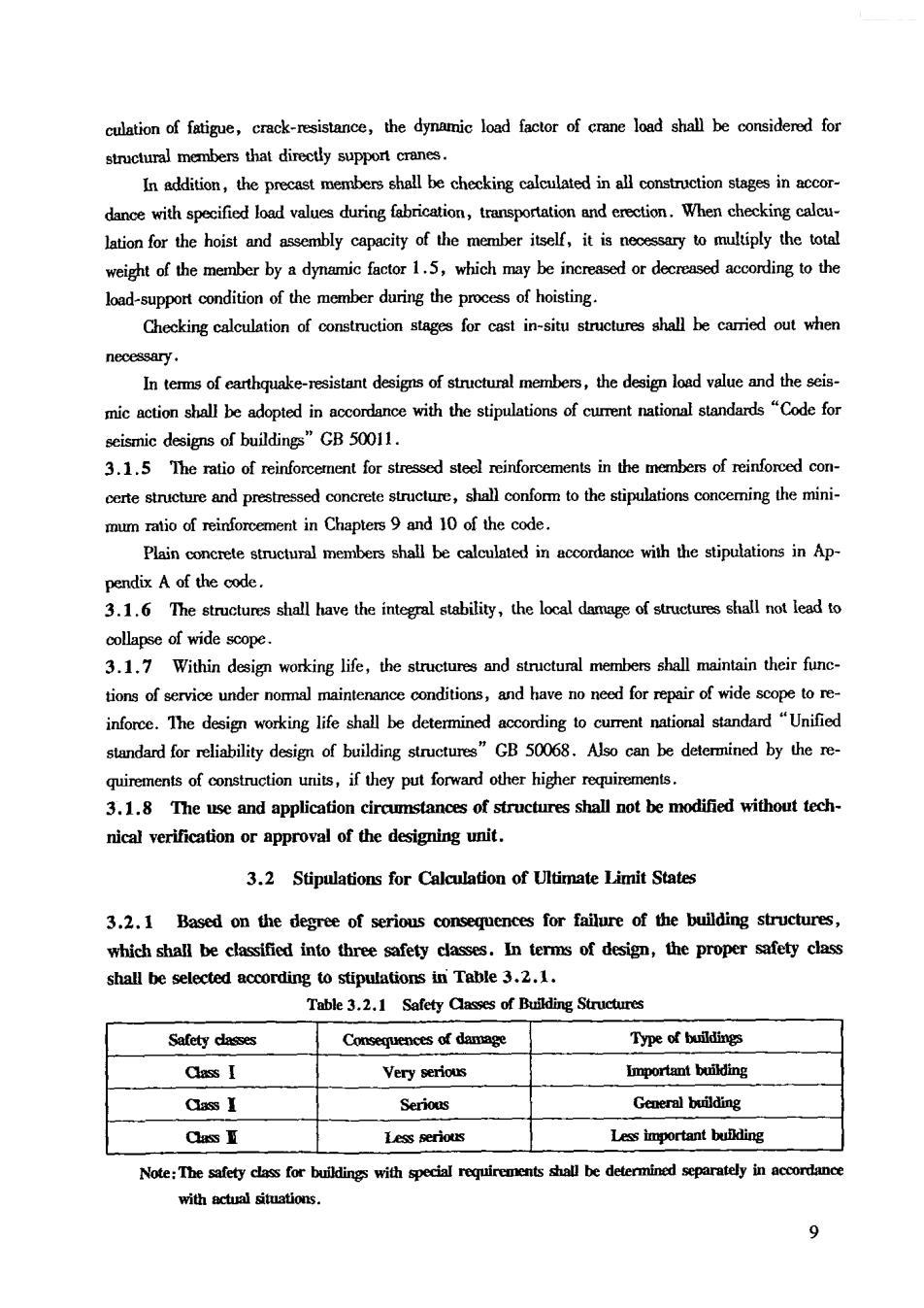
culation of fatigue,crack-resistance,the dynamic load factor of crane load shall be considerd for structural members that directly suppon cranes. In addition,the precast members shalbe checking stages in dance with specified load values during fabrication,transportation and erection.When checking calcu- lation for the hoist and assembly capacity of the member itself,it isn ary tomultiply the tot weight of the member by a dynamic factor1.5,which may be increasedodecresdaccording tothe load-support condition of the member during the process of hoisting. Checking calculation of construction stages for cast in-situ structures shall be carried out when necessary. In tems of earthquake-esstant designs of stuctural members,the design load valuc and mic action shall be adopted in accordance with the stipulations of cumrent national standards"Code for scismic designs of buildings"GB 50011 3.1.5 The ratio of reinforcement for stressed steel reinforcements in the members of reinforced con- certe structure and prestressed concrete,shall confor to the stipulations conceming the mini- Plain concrete structural members shall be calculated in accordance with the stipulations in Ap pendix A of the code 3.1.6 The structures shall have the integral stability,the local damage of structures shall not lead to collapse of wide scope 3.1.7 Within design working life,the structures and structural members shall maintain their func- tions of srvice under noal maintenance,and havenoned for repair of wide scopetor inforce.The design working life shall be determined according to current national standard "Unified stndard for reliability design of".Also can be determind by there quirements of construction units,if they ther higher. 3.1.8 The use and application circumstances of structures shall not be modified without tech nical verification or approval of the designing unit. 3.2 Stipulations for Calculation of Ultimate Limit States 3.2.1 Based on the degree of serious consequences for failure of the building structures, which shall be classified into three safety classes.In terms of design,the proper safety class shall be selected according to stipulations in Table 3.2.1. Table 3.2.1 Safety Classes of Building Structure Safety dasses Type of buildings Class I Very serio Ciass I Serious General building Qas亚 Less serios Les important buikding with actual situations. 9
3.2.2 Safety classes of all building structural membersarequird to be the sme as afety css for the integral structure.While safety classes for some structural members can be readjusted appropn- ately in accordance with their degree of significance,but it cannot be readjusted to less than class 3.2.3 For ultimate limit states,the structural members of building structures shall accord with the fundamenial combination of d-cttoadopt the following xpres sions of limit states: (3.2.3-1) R=R(fe,f,a4…) (3.2.3-2) Where ofactor of importance:for structural members of safety class Ior the design servce year is 100 years or above shall not be less than 1.1;for structural members of safety class II or the design service year is 50 years,shall not be less thanl.0;for structural members of safety class IIIor the design see year is less than 5years,shall not be less than 0.9;in earthquake-resistant design,the factor of importance for structural members may not be S-Design values for combination of load-effects for ultimate limit states,which are cal- culated in accordance with the cuent National Standards"Load code for design of building structures"GB 50009,and "Code for seismic design of buildings"GB 50011; R-Design values of loading-bearing capacity of structural members;in the earthquake-re- sistant design,the value of R shall be divided by the earthquake-resistant adjusted oefficient E of load bearing capacity; R(·) -function of load-bearing capacity of structural member; -design value of strength strengh of: ak- characteristic value of geometric prmeter.When the variation ofthegmei pa- rameter significantly influences structural behavior,ak may be increased or decreased o in equation(3.2.3-1)is expresd by design values of intema fores(N、M、V、Tctc.) in the ce Prestress-effects shall be considered for presrsde structures in accordance with the stipulntions for Clause 6.1.1 of the code. 3.3 Stipulations for Checking Calculation of Serviceability Limit States 3.3.1 For serviceability limit states,the structural members of building structures shall accord with the haracerisicomniqua-emanetomnnchriombinationandnr ng of long-term actions of load-effects,to adopt the following design limit states: S≤C (3.3.1) where S- -denotes the combination values of load-fects of serviceability limit states; 10
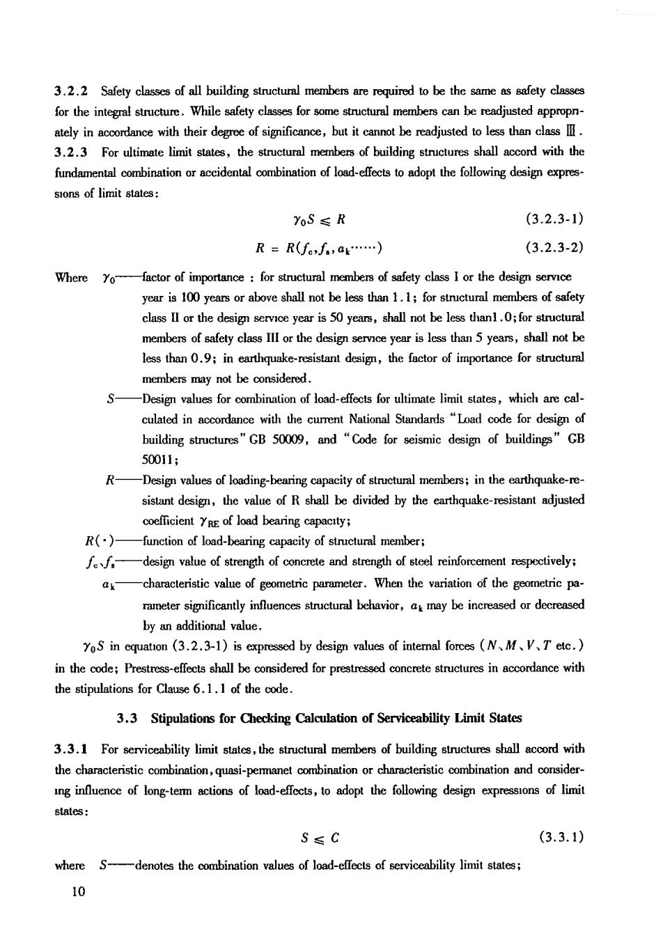
C-denotes the limiting values of deformation,width of cracks and stress etc,when the of the stipulated service ability. The characteristic and quasi-permanent combination of shall be ed in acordance with current nation stndards"Load code for design of building structures"GB 50009. 3.3.2 Maximum deflection of flexural member shall be calculated in accordance with the characteris- tic combination and considering infuence of long-term actions of load-effects,its calculated value shall not exced the allowable limiting values of deflection stipulated in the Table3.3.2. Table 3.3.2 Deflection Vakes for Members Type of meanbers Limiting values of deflection L/500 Electric-operated crane l6/600 Roof,floors and stair members: e 6<7m L200(Ln250) When 7m≤0≤9四 6/250(l6/300) When lox9m 1300(1/400) Note:1 the Table isthe spn 2 Values in parenthess are appropriate for membersonwhich the deflections are sricty required in applica value shall be deducted from the calculated deflection value during checking calculation with the allowable actual length of camilever. 3.3.3 Crack control level for nomal section of structural members shall be divided into three levels in accordance with the following stipulations: Level -members,on which cracks are strictly prohibited,when the calculation is in accor- dance with characteristic combination of load-effects,that the tensile stress shall not beoccured at ex treme tensile fiber of conerete structural members; dance with characteristic combination of load-effects,that the tensile stress at extreme tensile fiber of be greater than the characteristic value of aal tensile strength in concrete;when the calculation is in accordance with qunsi-permanent combination of load-effects,that the tensile stress at tensile fiber members may ot,but itcar be loosened,when the reliable experiences are available. Level 3- -members,on which cracks are allowed,when the calculation is in accordance with 11
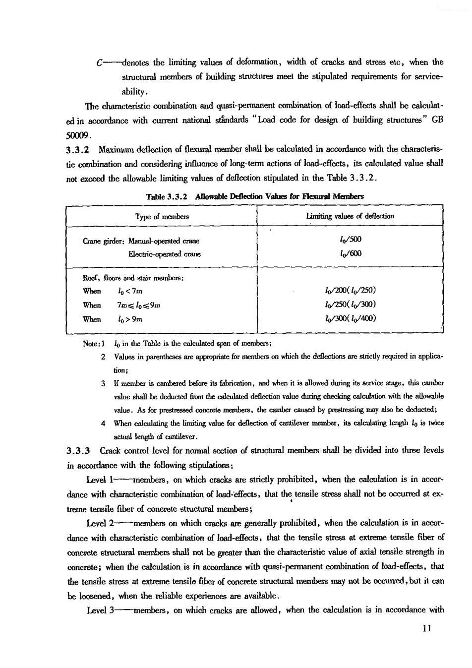
characteristic combination and considering influence of long-term actions of load-effects,that the maxi- mumcrack width of structural members shall not exceed the stipulated limit values of maxmum crack width given in the Table 3.3.4. 3.3.4 The different crack control levels and the limit values of maximum crack width of struc- tural members shall be adopted from the Table 3.3.ng to the types of and the e ronmental categones spccified in the Table 3.4.1. Table 3.3.4 Crack Control Levels and Limit Values of Maxinmm Crack Width Environmental Reinfomed concrete structurea Prestreased concrete structures Crack onro leves oa(mm) Crack levels (mml) ® 0.3(0.4) 0.2 、0 0.2 I 血 0.2 I Note:lThestinlaionsintheTablearespliceabletoeintoroedconcretemenbecsusinghdtoledstedbars,ans to prestressed concrete members using prestressed steel wires,strand,heat treated steel bars;when othe types of steel wires or reinforcements are selected,the roquirements of crack control may be determined by 2 less than 60%,the value in parerhesis may be used as its limit value of maximum crack width: forced concr and0.3mm'shal be adopted for reinforoed concrete rofing beam and bracket beam; Under level l em I and I environments,the fatigue of preatressed conrete crane girder shall be checking calcuated ac 5 The crack co structural member,are merely applicable to checking calculation of nommal sction.The checking ca 6 quirements shallonfo to relevant provisors of cumrent special code: 8 The limit values of maximum crack width in the Tableare usedfor the checking calculation of mximum 3.4 Stipulations for Durability 3.4.1 The durability of concrete structures shall be designed in accordance with the environmental categons and design working life specified in the Table 3.4.1. 12
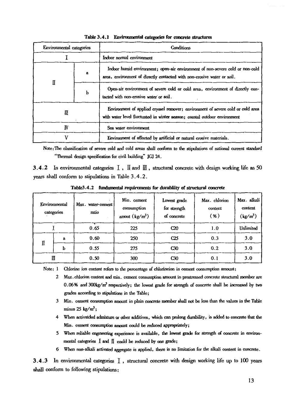
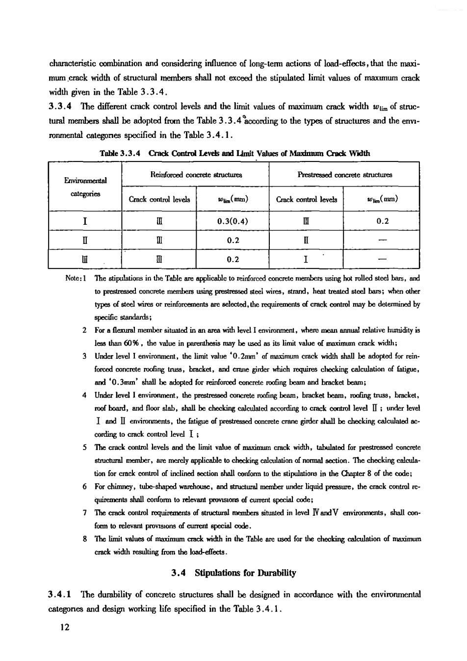
Table 3.4.1 Envirommental categories for concrete structures Environmental categories Conditions ndornoemalcnvionmet Indor humid nrmentopenviroment of nosevere cold oronod ronment of directly otactedwihnonreosf water or soil. tacted with non-erosive water'or soil. with water level fluctuated in winter season:coastal outdoor environment W Environment of affected by artificial tua erive maeri Note:The classification of evee cold and cold reas shalonfo tothe stipulations of ntion cuenadrd "Themal desi specification for civil building"JGJ 24. 3.4.2 In ervironmental categories I,II and I,structural concrete with design working life as 50 years shall conform to stipulations in Table 3.4.2. Min.cement Lowest grade Max.chlorion Max.alkoli mtio amout (kg/m') of concrete (%) (kg/m) 0.65 225 C20 1.0 Unlimited a 0.60 250 25 0.3 3.0 b 0.55 275 C30 0.2 3.0 0.50 300 C30 0.1 3.0 Note:1 Chlorine ion o refers to the percentage of chlorineion in menonmtionu 2 Mat chlorion content and min dedingtostipulations in the Table: 3 minus 25 kg/m 4 When activadodixturetheraddtives,whichca prolongdurability,isddd tooethat the Min.cenenlcoreumptionamountcoudldberotdicodappoprilely: mental categories I and coud be reduced by one grade; 3.4.3 In environmental categories I,structural concrete with design working life up to 100 years shall confom to following stipulations: 13