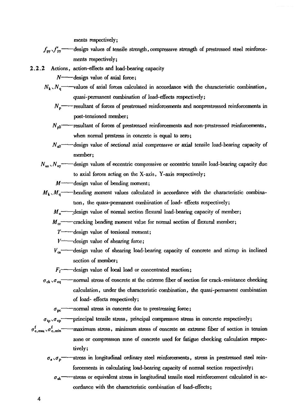
ments respectively: design values of tensile strength,compressive strength of prestressed steel reinforce ments respectively; 2.2.2 Actions,action-effects and load-bearing capacity N-design value of axial force; Nk、Ng -values of axial fores calculated in accordance with the characteristic combination, quasi-permanent combination of load-effects repectively; Nresulant of fores of prestressed reinforcements and nonprestressed reinforcements in post-tensioned member; resultant offorces of prestressed reinforcements and non-prestressed reinforcements when nommal prestress in concrete is equal to zero; design value of sectiona axial compressive or ial tensile load-bearing capacity of member; NN-design values of eccentric compressive or cccentric tensile load-bearing capacity due to axial forces acting on the X-axis,Y-axis respectively: M-design value of bending moment; MMbending moment values calculated in accordance with the characteristic combina- ton,the quasi-permanent combination of load-effects respectively; value of nommal section flexural load-bearing capacity of member; cracking bending moment vale for normal member; -design value of torsional moment: V- -design value of shearing force; Va -design value of shearing load-bearing capacity of and stirup in inclined section of member; F-design value of local load or concentrated reaction; nomal stress of concrete at the extreme fiber of section for crack-resistance checking ,under the,the quas-peanentmnio of load-effects respectively: penormal stress in concrete due to prestressing force; principal tensile sess,principal in concrete respectively; c,.min -maximum stress,minimum sress of concreteon extreme fiber of sction in tension of for fatigue checking tively; stress in longitudinal ordinary steel reinforcements,stress in prestressed steel rein forcements in d-bearing capacity of stress or equivalent stress in longitudinal tensile steel reinforcement calculated in ac- cordance with the characteristic cominaioof load-effecs; 4
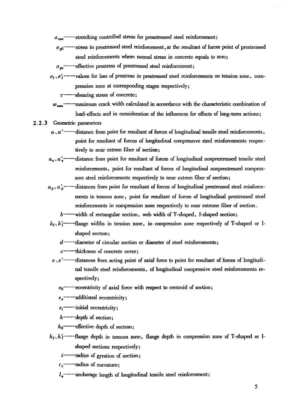
‘,o—stnesinprstnsodstedlreinlfoement,ttherstltamntodforcspointofprestresed steel reinforcements where nomal stress in concrete equals toero -effective prestress of prestressed steel reinforcement; values for loss of prestress in prestressed steel reinforcements on tension one,com- pression one at comesponding stages respectively; -shearing stress of concrete; 1 oex -maximum crack width calculated in accordance with the characteristic combination of load-efects and in consideration of the influences for effects of long-term actions; 2.2.3 Geometric parameters a、a' -distance from point for resulant of forces of longitudinal tensile steel reinforements pointfor longitudinal tively to near extrem fiber of section; reinforemn,point for eanofores of longitudinal nonpredcomprs- sive steel reinforcements respectively to near extrem fiber of section; distances from point for resuant of forces of longitudina menisin tenso oe,point for eoffores of longitudinal prestressd stee reinforcements in compression zone respectively to near extreme fiber of section. b width of rectangular sectio,web width of T-shaped,I-shaped ctio bbfange widths in tension zone,in compression zone respectively of T-shaped or I- shaped section; d -thickness of concrete cover; ating point of axial force to point for suant offor of longitudi nal tensile steel reinforcements,of longitudinal compressive steel reinforcements re- co- eccentricity of axial force with respect to cenid -additional eccentricity; einitial eccentricity; h -depth of section; ho -effective depth of secon; fange depth in tension zone,flange depth in compression zone of T-shaped or I- shaped sections respectively; i radius of gyration ofct -radius of curvature -anchorage length of longitudinal tensile steel reinforcement; 5
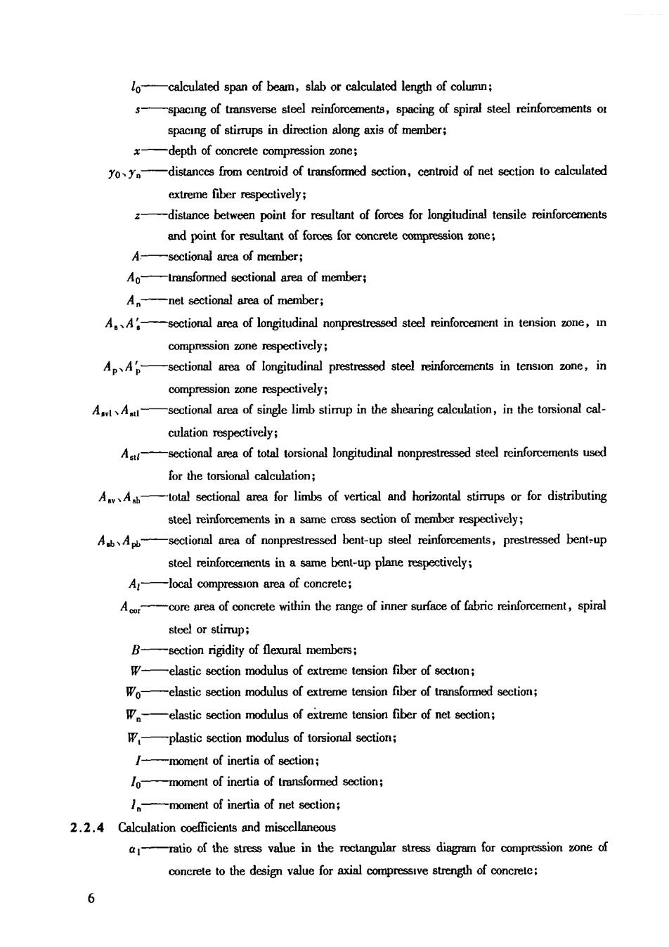
localculated span of beam,slab or calculated length of column; spacng of transverse se rinforments,spacing of spiral steel reinforementso spacing of stirrups in direction along axis of member; depth of concrete compression zone; distancesfrom centoid of ransformed section,centroid of net section to calculated extreme fiber respectively; distance between point for resultant of forces for longitudinal tensile reinforcements and point for concrete compression o A -sectional area of member; Ao -transfored sectional rea of member Anet sectional area of member; A.Asectional area of longitudinal nonprestressed steel reinforcement in tension zone,n compression zone respectively; of longitudinal prestressed steel reinforements in,in compression one respectively Al、Aul -sectional area of single limb stirrup in the shearing calculation,in the torsional cal- culation respectively; A -of total torsional longitudinal nonprestressed steel rinforcements used for the torsional calculation; sectional area for limbs of vertical and horizontal stirrups or for distributing Ab、Ab sectional area of nonprestressed bent-up steel reinforements,prestressed bent-up steel reinforcements in a same bent-up plane respectively; A -loca compression area of concrete; stee or stimupi section rigidity of flexural members; Woelastic section modulus of extreme tension fiber of transformed section: W -elastic section modulus of extreme tension fiber of net section; Wplastic section modulus of torsional section; mment of inertia of section; moment of inertia of transformed section; 1。 -moment of inertia of net section; 2.2.4 Calculation coefficients and miscellaneous the stress value in the rctangular stress diagram for of concrete to the design value for axial compressive strength of concrete; 6
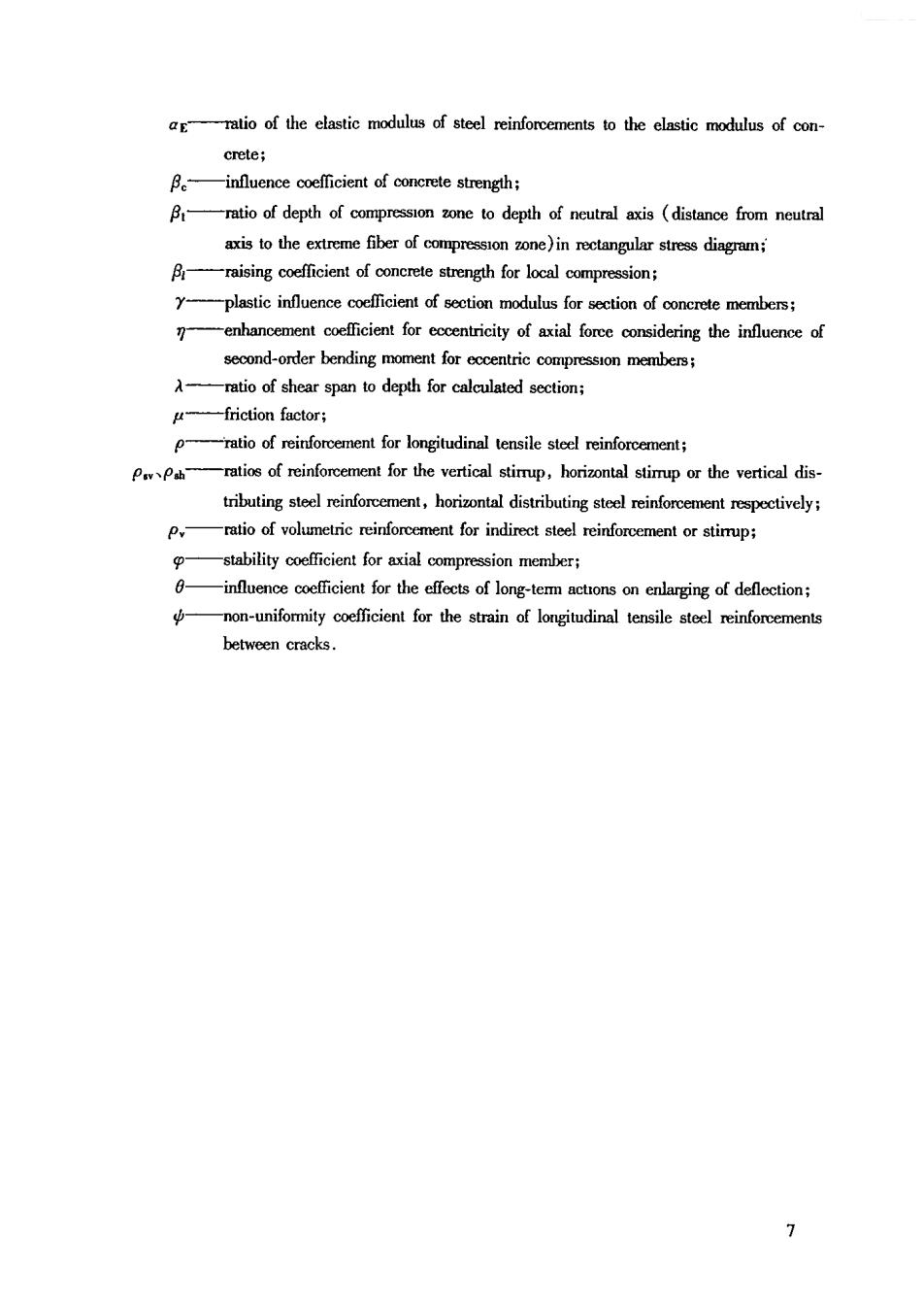
-ratio of the elastic modulus of steel reinforcements to the elastic modulus of con crete; ratio of depth of compressono to depth of neutral axis(distance from neutral axis to the extreme fiber of compression zone)in rectangular stress diagram; -plastic influence of sction modulus for sction of members -enhancement coefficient for eccentricity of axial force considering the influence of -ratio of shear span to depth for calculated section; μ -friction factor; 0 ratio of reinforcement for longitudinal tensile steel reinforcement; ratios of the vertical stimup,horizontal the vertical dis tributingstehorinta distributingstspectively P ratio of volmetricreinforcement for indirect steel reinforcemen orstirrup; -influence coefficient for the effects of long-term actions on enlarging of deflection; non-uniformity for the strain of longitudinal tensile steel reinforcement between cracks. 1
3 Fundamental Design Stipulations 3.1 General Stipulations 3.1.1 The code adopts the probability-based limit states design method,the degree of reliability of structural members is measured by the reliability index,and the design is carried out by adopting the design expressions of partial safety factors. 3.1.2 When a sucture or part of a structure xcding a particular state,that a certain functional requirement in design stipulations will be dissatisfied,hence this particular state is called the limit function The limit statesre classified as two categories asfollo: 1 Ultimate limit states:Asrcturera structural member reaches the maximum load-bearing capacity,and appears the fatigue failure or undue defommation unsuitable for loading continuously; 2 Serviceability limit sats:Astructurerastructura member reaches a certain stipulated limit value of srviceability or durability 3.1.3 In accordance with requirements of ultimate and serviceability limit states,the structural members shall be and checking on the basis of the following stipulations: 1 Load-bearing capacity and stability:All structural members shall be calculated in accordance with load-bearing capacity(including instability);cases,structural overtuming,floatingand sliding shall also be checking calculated; In addition,the earthquake-resistant capacity of structural members shall still be checking calcu lated for structures inares subject to seismic activity 2 Fatigue:The fatigue strength of structural members,which directly support heavy-duty cranes,shall be checking depending on actual application and design the members,which directly support cranes used for installation or maintenance,may be exempted from checking on the fatigue strength of members 3 Deformation:Deformation checking calculation shall be carried on structural members,where the defomation values need be during srvice; 4 Crack-resistance and erack width:The checking calculation for tensile stress of concrete shall be carried on the stuaturalmember,where crack isnot allowed during service;in cases where crack is permitted during sevice,the crack width of members shall be checking calculated;in addition,the checking calculation for tensile stress of longitudinal steel reinforcement in the superposed flexural 3.1.4 The design values of loads shall be used when calculating the load-bearing capacity(including instability),and in checking overtuming,; ing representative valucs of loads shall be used for all checking calculations such as fatigue,deforma- tion,crack-sistance and crack width;when calculating the load-bearing capacity,and checking cal- &