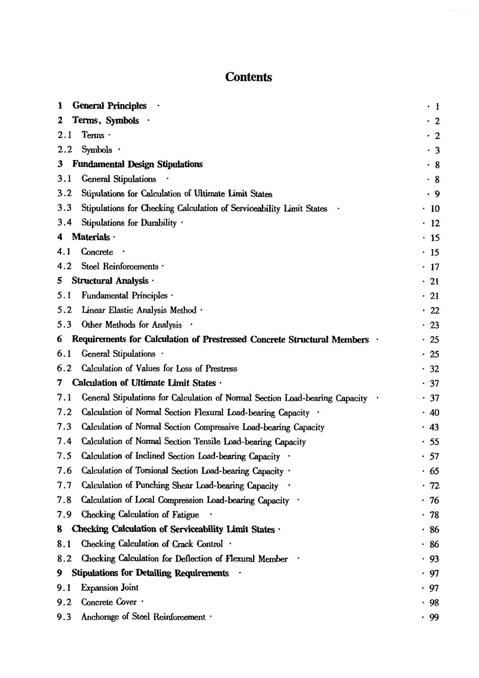
Contents 1 General Principles 2 Terms,Symbols 2 2.】Tems 2 2.2 Symbols· 3 Fundamental Design Stipulations 8 3.1 General Stipulations .8 3.2 Stipulations for Calculation of Ultimale Limit States 9 3.3 Stipulations for Checking Calculation of Serviceability Limit States .10 3.4 Stipulations for Durability ·2 4 Materials· .15 4.1 Concrete ·15 4.2 Steel Reinforcements .1 5 Structural Analysis. ·21 5.1 Fundamental Principles 21 5.2 Linear Elastic Analysis Method 、22 5.3 Other Methods for Analysis 23 6 Requirements for Calculation of Prestressed Concrete Structural Members. .25 6.1 General Stipulations 25 6.2 Calculation of Values for Loss of Prestress 32 7 Calculation of Ultimate Limit States 7.1 General Stipulations for Calculation of Nomal Section Load-bearing Capacity 37 7.2 Calculation of Nommal Section Flexural Load-bearing Capacity 7.3 Calculation of Normal Section Compressive Load-bearing Capacity 43 7.4 Calculation of Nommal Section Tensile Load-bearing Capacity 55 7.5 Calcultion of Inelined Section Load-bearing Capacity 57 7.6 Calculation of Torsional Section Load-bearing Capacity 6的 7.7 Calculation of Punching Shear Load-bearing Capacity , 7.8 Calculation of Local Compression Load-bearing Capacity ,76 7.9 Checking Calculation of Fatigue 78 8 Checking Calculation of Serviceability Limit States ·86 8.1 Checking Calculation of Crack Control 86 8.2 Checking Calculation for Deflection of Flexural Member ·93 9 Stipulations for Detailing Requirements 97 9.1 Expansion Joint .g7 9.2 Concrete Cover ·98 9.3 Anchorage of Steel Reinforcement .99

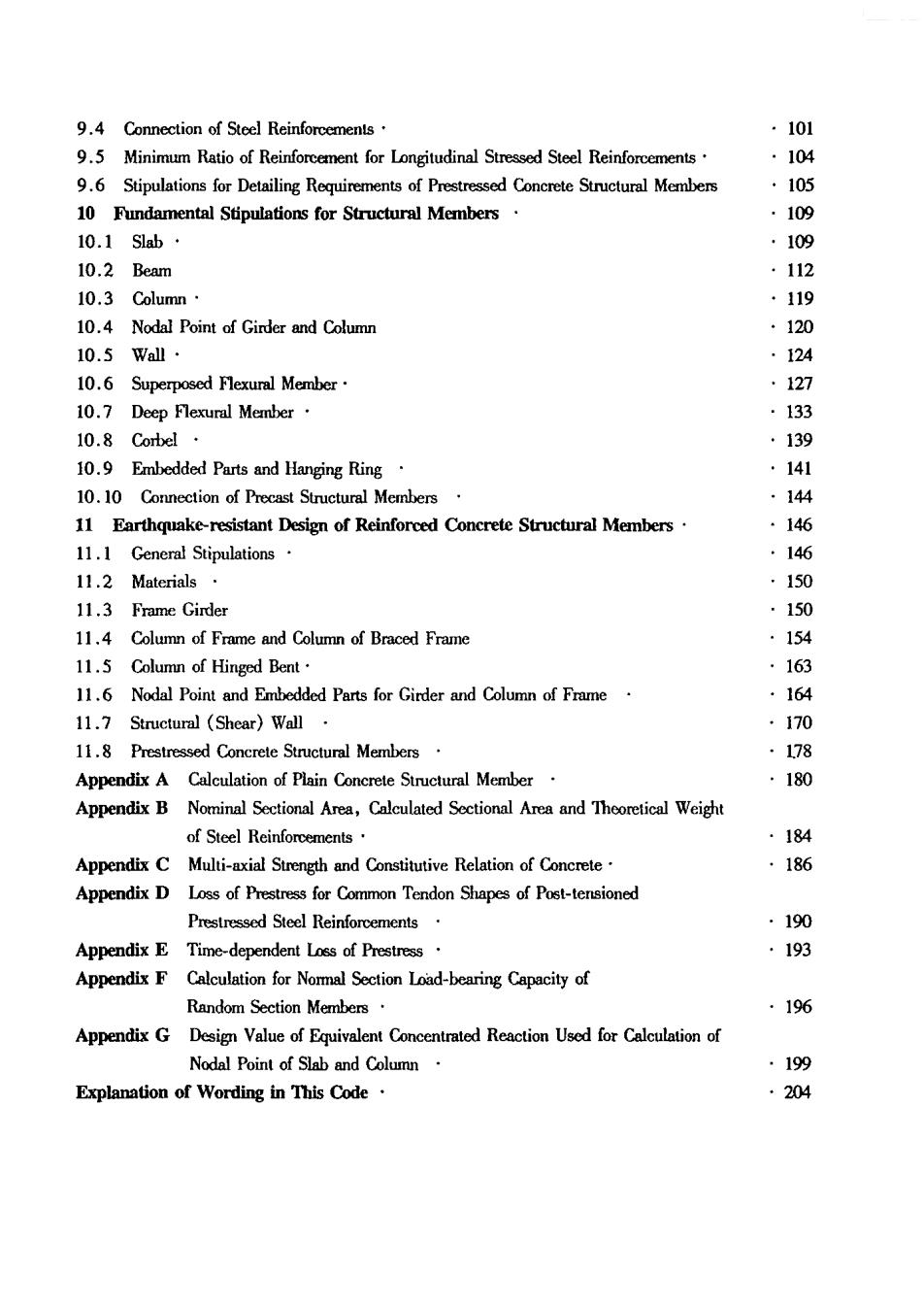
9.4 Connection of Stcel Reinforcements ·101 9.5 Minimum Ratio of Reinforcement for Longitudinal Stressed Steel Reinforcements. ·104 9.Stipulations for Detailing Requirements of Prestressd Conerete Stuctural Members ·105 10 Fundamental Stipulations for Structural Members 109 10.1Slab· ,109 10.2 Beam ·112 10.3 Column· 119 10.4 Nodal Point of Ginder and Columr 120 10.5Wall· 124 10.6 Superposed Flexurl Member 127 10.7 Deep Flexural Member 133 10.8 139 10.9 Embedded Parts and Hanging Ring 141 10.10 Connection of Precast Structural Members 144 11 Earthquake-resistant Design of Reinforced Concrete Structural Members 146 11.1 General Stipulations. 11.2 Materials. 150 11.3 Frame Girder 11.4 Column of Frame and Column of Braced Frame 154 11.5 Column of Hinged Bent. 163 11.6 Nodal Point and Embedded Parts for Girder and Column of Frame 164 11.7 Structural (Shear)Wall 170 11.8 Prestressed Concrete Structural Members 8 Appendix A Calculation of Plain Concrete Suructural Member 180 Appendix B Nominal Sectional Area,Calculated Sectional Area and Theoretical Weight of Steel Reinforements ·184 Appendix C Multi-axial Strength and Constitutive Relation of Concrete .186 Appendix D Loss of Prestress for Common Tendon Shapes of Post-tersioned Prestressed Steel Reinforcements ·190 Appendix E Time-dependent Loss of Prestress 193 Appendix F Calculation for Nommal Section Load-bearing Capacity of Random Section Members 196 Appendix G Design Value of Equivalent Concentrated Reaction Used for Calculation of Nodal Point of Slab and Column ·199 Explanation of Wording in This Code. .204

1 General Principles 1.0.1 The cde was published national technical and policies for the design of concrete sructures,and to ensure structures to be economical,reasonable,reliable,applica- ble,with high quality and using advanced technology. 1.0.2 The code is applicable to the design of reinforcedcone,prestressone and plain concrete load-bearing structures used in industrial and civil buildings,as well as normally constructed structures,but it is not applicable to the design of lightweight aggregate concrete structures,or struc tures using special concrete. 1.0.3 In design besides cmying with the stipulations in the cde the de- sgners shall also confom to the stipulations in relevant current mandatory national standards. 1

2 Terms,Symbols 2.1 Terms 2.1.1 Concrete structures-The structures are mainly made by concrete,including plain concrete stucture,reinforced concrete structure,and prestressed concrete structure etc. 2.1.2 Plain concrete structure-The structure is made of the concrete without the stcel reinforcements or not providing with the stressed steel reinforcements. 2.1.3 Reinfored concrete structure-The structure is made of the and providing with the stressed ordinary steel reinforcements,steel reinforcement meshs or steel reinforcement skeletons. 2.1.4 Prestressed concrete structure-The structure is made of the concrete and providing with the stressed prestressing reinforcements,which will be through stretching or by other methods to establish prestress. 2.1.5 Pre-tensioned prestressed structure-The concrete structure of which the concrete will be casted,after the stressed prestressing reinforcements have been stretched on stretching bed,then thu the transmission of ond force between tendons and conrete to establish prestress 2.1.6 Post-tensioned prestressed concrete structure-The concrete structure of which the strength of concrete should be first reached the required stipulated requirements,then stretching the stressed pre- stressing reinforcements and anchoring on the structure to establish prestress. 2.1.7 Cast-in-itcontetre-Thecor of hi the fomork stalled in-situ and cast-in-situ the concrete integrally. 2.1.8 Prefabricated concrete sructur-The concretesucture of which the structure is assembled by 2.1.9 Assembled monolithic concrete structure-The monolithic concrete structure is assembled by precasted concrete components or parts,through the connections of steel reinforcements,connecting parts or applied prestressing force,and finally cast-in-situ the concrete. 2.1.10 Frame structure-The load-bearing system structure is compeed by girders and columns con- necting them with rigid joint or hinged jo. 2.1.11 Suructural (shear)wall structure-The structure is composed by structural wall (shear wall)to sustain the vertical and horizontal actions. 2.1.12 Frame-structural (shear)wall structure-The structure of which the vertical and horizontal ac- tions are jointly sustained by frame and structural wall (shear wall). 2.1.13 Deep flexural member-It denotes the flexural member with span-depth ratio less than 5. 2.1.14 Deep beam-denotes the single-span beam with span-depth ratio not greater than 2 and the multi-spn beam with span-depth ratio not greater than 2.5. 2.1.15 Ordinary steel bar-A general call for various non-prestressed steel reinforcements which are used in concrete structural members

CEPIC 2.1.16 Prestressing steel reinforcements-A general call for steel bars,steel wires,and strands which are used in the prestressed concrete structural members. 2.1.17 Degree of reliability-It refers to the measurement for the probability of which the ability of a structure fulfils the expected functions within stipulated time-limil and stipulated conditions. 2.1.18 Safety class-The classes of structures and structural members which are classified according to the degre of severity for the destructive 2.1.19 Design working life-The design stipulation for the time-limit of working period of structures or structural mmbers,which can serve for the expected have no ned of 2.1.20 Load-effect-The reactivity of the structures and structural members are induced by loads. such as defomations and cracks etc. 2.1.21 Combination of load-effects-In the limit states design,it is the stipulated combination for de sign valucs of various load,tos the rliability of the stuctures. 2.1.22 Fundamental combination-It refers to the combination of permanent loads and variable loads in the calculation of utimate limit states. 2.1.23 Characteristic combinntion-In the checking calculation of serviceability limit states,that the characteristic values and combination values of variable loads are used as the represenive values of variable loads in combination. 2.1.24 Quasi-permanent combination-In the checking calculation of serviceability limit states,that theuas-pemanent values of variable oadsareused as the represenative values of the variable loads in combination. 2.2 Symbols 2.2.1 Material properties -modulus of clasticity of concrete; E modulus of fatigue deformation of concrete; E. C20 strength grade with characteristic value of cube/mm fa -compressive strength of 150mm side length concrete cube during period of construc tion; characteristic value side fcharacteristic value,design value of axial compressive strength of concrete respec tively; characteristic valucs of axil comressive strength,axial tensile strength of conret during period of construction respectively; fkJu一 characteristic values of strength of ordinary steel reinforements,prestressed stee design values of tensile strength,compressive strength of ordinary steel reinforce