
Particle Cutting For particle,surface areas is created and Stacking Faults For chemically ordered particle,also creates APBs. Slip band Particle 200nm Meyers and Chawla,Mechanical Metallurgy Only for coherent/semicoherent precipitates!!
Particle Cutting 12 For particle, surface areas is created and Stacking Faults For chemically ordered particle, also creates APBs. Meyers and Chawla, Mechanical Metallurgy Only for coherent/semicoherent precipitates!!
Dislocation-Particle Interactions Hard precipitates are difficult to shear. Ex:Ceramics in metals(SiC in Iron or Aluminum). precipitate Large shear stress needed Side View to move dislocation toward grecipitate and shearit. Unipped part of slip plane Top View Dislocation “advances”but precipitates act as “pinning”sites with spacing S. Spped part of slip plane ·Result: y Why?
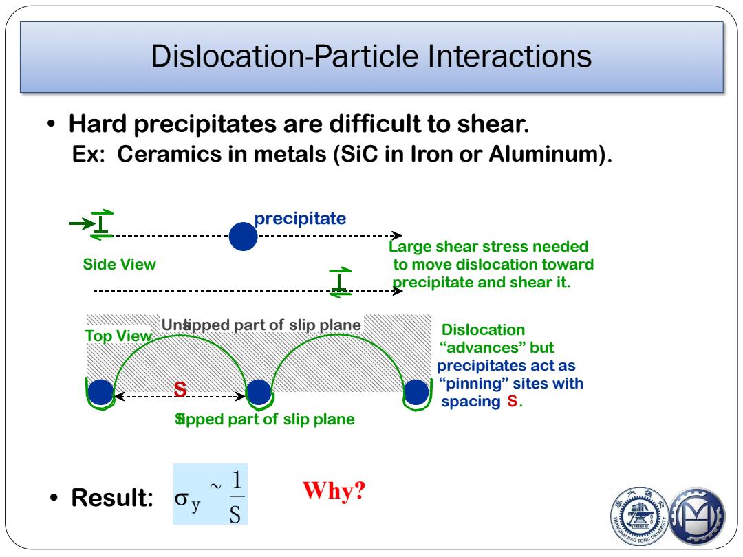
Dislocation-Particle Interactions 13 • Hard precipitates are difficult to shear. Ex: Ceramics in metals (SiC in Iron or Aluminum). • Result: y ~ 1 S Why? Large shear stress needed to move dislocation toward precipitate and shear it. Side View Top View Slipped part of slip plane Unslipped part of slip plane S Dislocation “advances” but precipitates act as “pinning” sites with spacing S. precipitate
Bowing vs.Cutting If the particle is harder than matrix,dislocation can avoid cutting by bowing around particle,or traversing around particle at interphase boundary (a complex process). Gb 1-2r Harder to cut stiffer,larger particles. Easy to bow around stiffer,larger particles. Crossover O Orowan mechanism Gbf r<<l TOR 0.1m O TONG
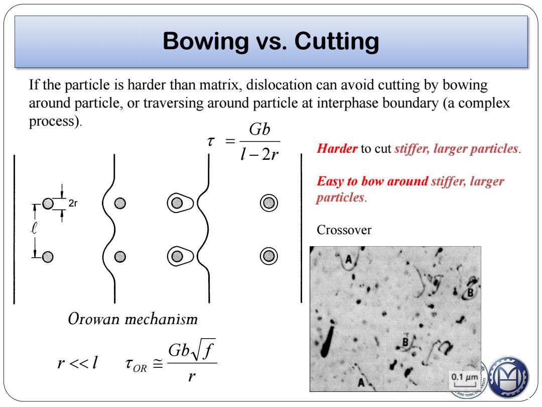
Bowing vs. Cutting 14 If the particle is harder than matrix, dislocation can avoid cutting by bowing around particle, or traversing around particle at interphase boundary (a complex process). Harder to cut stif er, larger particles. Easy to bow around stif er, larger particles. Crossover Orowan mechanism 2r l r Gb 2 r Gb f r l OR

Initial configuration A B Dislocation line segment pinned at A and B by precipitates Application of stress on dislocation segment Line tension H B Bowing ↑ Force=tb As the dislocation line gets curved the energy of the system increases work has to be done by external stresses to cause this extension. Line tension (opposes the shear stress on the slip plane (7).At a given stress there might be a balances of forces leading to a curved geometry of the dislocation line. Further extension of the dislocation line occurs by increasing the stress
Initial configuration A B Dislocation line segment pinned at A and B by precipitates A B Force = b Application of stress on dislocation segment Line tension Bowing § As the dislocation line gets curved the energy of the system increases work has to be done by external stresses to cause this extension. § Line tension (opposes the shear stress on the slip plane (). At a given stress there might be a balances of forces leading to a curved geometry of the dislocation line. § Further extension of the dislocation line occurs by increasing the stress

L and-segments come together and annul each other H→ tb Direction of dislocation motion is I to the dislocation line (except at A and B) 4 Original segment semicircle-→ corresponds to maximum stress required to expand the loop After this decreasing stress is required to expand the loop ◆New loop created
b b b L I n c r e a s i n g s t r e s s semicircle→ corresponds to maximum stress required to expand the loop After this decreasing stress is required to expand the loop Direction of dislocation motion is to the dislocation line (except at A and B) 3 2 1 4 5 Original segment New loop created + + and segments come together and annul each other