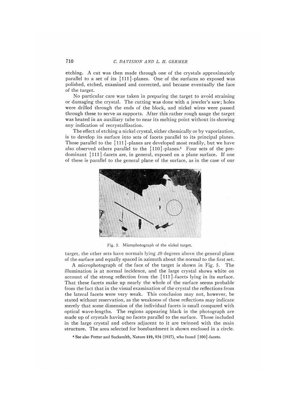
710 C.DAVISSON AND L.H.GERMER etching.A cut was then made through one of the crystals approximately parallel to a set of its 111-planes.One of the surfaces so exposed was polished,etched,examined and corrected,and became eventually the face of the target. No particular care was taken in preparing the target to avoid straining or damaging the crystal.The cutting was done with a jeweler's saw;holes were drilled through the ends of the block,and nickel wires were passed through these to serve as supports.After this rather rough usage the target was heated in an auxiliary tube to near its melting point without its showing any indication of recrystallization. The effect of etching a nickel crystal,either chemically or by vaporization, is to develop its surface into sets of facets parallel to its principal planes. Those parallel to the 111-planes are developed most readily,but we have also observed others parallel to the 110-planes.4 Four sets of the pre- dominant 111-facets are,in general,exposed on a plane surface.If one of these is parallel to the general plane of the surface,as in the case of our Fig.5.Microphotograph of the nickel target. target,the other sets have normals lying 20 degrees above the general plane of the surface and equally spaced in azimuth about the normal to the first set. A microphotograph of the face of the target is shown in Fig.5.The illumination is at normal incidence,and the large crystal shows white on account of the strong reflection from the 111-facets lying in its surface. That these facets make up nearly the whole of the surface seems probable from the fact that in the visual examination of the crystal the reflections from the lateral facets were very weak.This conclusion may not,however,be stated without reservation,as the weakness of these refections may indicate merely that some dimension of the individual facets is small compared with optical wave-lengths.The regions appearing black in the photograph are made up of crystals having no facets parallel to the surface.Those included in the large crystal and others adjacent to it are twinned with the main structure.The area selected for bombardment is shown enclosed in a circle. See also Potter and Sucksmith,Nature 119,924(1927),who found 100)-facets
DIFFRACTION OF ELECTRONS BY A NICKEL CRYSTAL 711 The target was mounted in a holder from which it was insulated,and the holder was fixed to the end of a hollow shaft mounted in bearings A small tungsten filament mounted back of the target(not shown in Fig.2) supplies electrons for heating the target by bombardment.Leads from the target and from this filament pass out through the hollow shaft and are connected through platinum brush contacts to other leads which are carried through seals in the tube. The mechanism for rotating the target is shown in Figs.2 and 4.When the tube is rotated counter-clockwise about the collector axis,to bring the collector into range in front of the target,the molybdenum plunger p(at- tached to a heavy pendulum)passes through an opening in a toothed wheel (attached to the shaft)and engages with a milled edge of a strip of molyb- denum that is attached to the frame.The wheel and the target are then locked to the frame.When the tube is rotated clockwise until the main or longitudinal axis of the tube has passed slightly beyond the horizontal, the plunger disengages from the milled edge but still remains within the opening in the toothed wheel.The pendulum has a second degree of freedom (it revolves about a fixed hollow shaft coaxial with the shaft carrying the target)so that,by rotating the tube about its main axis,the pendulum and engaged wheel are rotated relative to the frame.The range of this rotation is only 20 or 30,but by rotating the tube slightly further in the clockwise direction about the collector axis the plunger is disengaged from the wheel, and can be moved,by rotation again about the main axis,to a different opening in the toothed wheel.By these operations the target can be worked through any angle.Its azimuth is read from a scale ruled on the wheel. This scale and that for reading the position of the collector are shown in Fig.4.The bearings throughout the tube,with the exception of one nickel on nickel bearing,are either molybdenum on molybdenum,or molybdenum on nickel. PREPARATION OF THE TUBE The metal parts of the tube were preheated to 1000C in a vacuum oven, and were then assembled and sealed into the bulb with the least possible delay.The bulb is of Pyrex and has sealed to it two auxiliary tubes,one containing cocoanut charcoal,and the other a misch metal vaporizer.This latter consists of a small pellet of misch metal attached to a molybdenum plate anode which may be bombarded from a nearby tungsten filament. The thermal contact between the pellet and the plate is reduced by the interposition of a narrow strip of molybdenum,so that the misch metal may be vaporized only by raising the plate to a very high temperature.The misch metal is vaporized when the pumping is nearly completed,and various of its constituents form solid compounds with the residual gas,thus improving and maintaining the vacuum. During the pumping,which lasted several days,the tube itself and the tubing connecting it with the pumps were baked for hours at a time at 5002C, and the side tube containing charcoal was baked at an even higher tem- perature-about 550C.This baking was alternated with heating by bom-
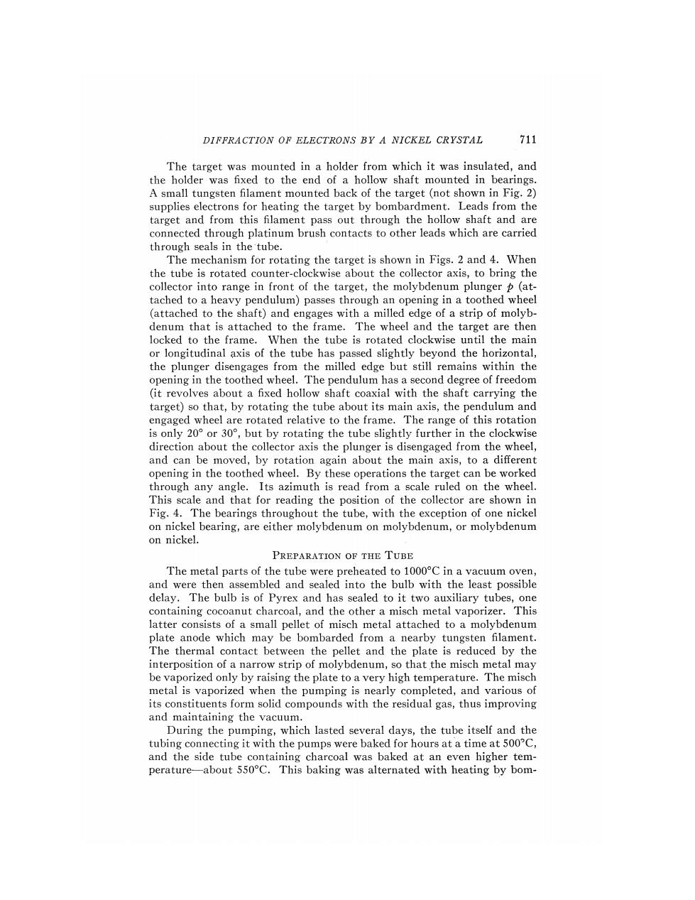
712 C.DAVISSON AND L.H.GERMER bardment of such of the metal parts as could be reached from the filaments. The target in particular was heated several times to a temperature at which it vaporized freely.The tube was sealed from the pumps with the target at a high temperature,and the charcoal at 400 or 500C and cooling.The pressure in the tube at the time was 2 or 3X10⁻⁶ mm of mercury.As soon as the tube containing charcoal had cooled sufficiently it was immersed in liquid air.No means were provided for measuring the pressure of the gas in the tube after sealing from the pumps,but from experience with similar tubes in which such measurements could be made we judge that its equilib- rium value was 10-s mm of mercury or less.The pumping equipment con- sisted of a three stage Gaede diffusion pump backed by a two stage oil pump. THE CRYSTAL It is important to have a clear picture of the arrangement of atoms presented to the incident beam by the crystal.The nickel crystal is of the ARRANGEMENT OF ATOMS AND DESIGNATION OF AZIMUTHS 1t业 (HO) (oo]- ① 00 ② ① ① ① 3 o}→ ② -{11o ① -① ① 3 3 3 tW- ② ② ① ⊙ ⑦ firo tio {I00 Fig.6. face-centered cubic type.The 111-plane is the plane of densest packing, and in this plane the atoms have a triangular arrangement.Looking directly downward onto a crystal cut to this plane(Fig.6)one sees the atoms of the second plane below the centers of alternate triangles of the first plane,and the atoms of the third plane below the centers of the remaining triangles The atoms of the fourth plane are below those of the first.The lines joining any second-layer atom with the three nearest first-layer atoms are 110- directions in the crystal,and the lines joining it with the three next-nearest surface atoms are the orthogonal100-directions.It will be convenient to refer to the azimuths of these latter directions as 100-azimuths.The azimuths of the 110-directions are also those of the three lateral 111- directions,already referred to,and we shall designate these as (111- azimuths.We need also a designation for the azimuths that bisect the dihedral angles between adjacent members of the two sets already specified. There are six such azimuths and they will be referred to as110-azimuths
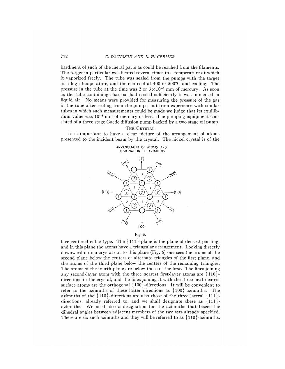
DIFFRACTION OF ELECTRONS BY A NICKEL CRYSTAL 713 It follows from the trigonal symmetry of the crystal that if the intensity of scattering exhibits a dependence on azimuth as we pass from a 100- azimuth to a next adjacent 111-azimuth(60),the same dependence must be exhibited in the reverse order as we continue on through 60 to the next following 100-azimuth.Dependence upon azimuth must be an even function of period 27/3. DISTRIBUTION OF SPEEDS AMONG SCATTERED ELECTRONS The electrons leaving the target in any given direction appear always to have speeds that are distributed in one of two ways,depending upon whether the direction lies within or outside a diffraction beam.In the latter CURVE I TOTAL SCATTERING CURVE I BEAM SCATTERING CURVEΠ BACKGROUND SCATTERING (INTERPOLATED) VOLTS 0 10 20 30 40 50 6070 COLLECTOR POTENTIAL Fig.7.Current to collector as a function of collector potential-bombarding potential 160 volts case-that of the electrons making up the "background"scattering-there is always a definite group having the speed of those in the incident beam. Below this speed there is in general a range over which the distribution in energy is very nearly uniform;and below this a range,ending with zero speed,in which the representation increases rapidly with decreasing energy. These characteristics are inferred from the relation between collector current and the potential of the collector relative to that of the filament. The lower portion of a typical curve exhibiting this relation for the "back- ground"scattering is shown in Fig.7(Curve II).The ordinate of a curve
714 C.DAVISSON AND L.H.GERMER of this sort is not,of course,an actual measure of the number of electrons entering the outer box with sufficient energy to reach the inner box.On account of the distortion of the field about the openings the probability that an electron entering the outer box with just sufficient energy to reach the walls of the inner box will actually do so is vanishingly small;the saturation current due to electrons of a given speed is attained only when the potential of the inner box is somewhat higher than that corresponding to their speed. The rounding off of the current-voltage curve at the top of the initial rise is due to some extent to this cause. For this reason the group of high speed,or full speed,electrons is more nearly homogeneous than would be inferred from the current-voltage curve if no account were taken of this distortion.It seems probable,in fact,that the distortion accounts almost completely for the rounding off of the curve, and that the group is as nearly homogeneous as is permitted by the drop in potential along the filament and the initial speeds of the emitted electrons. This view is strongly supported by the observations of Becker,5 Brown and Whiddington,Sharman,?and Brinsmades on the magnetic spectrum of electrons scattered by metals,and by similar curves obtained by Farns- worth.9 Within a diffraction-beam the distribution-in-speed is somewhat different. There is again a definite group of full speed electrons,but speeds just inferior to the maximum have much greater representation than among the back- ground electrons.This is inferred from curve III in Fig.7 which is repre- sentative of the current-voltage relation for electrons of this class.We shall return in a later section to a further consideration of the curves in this figure. In studying the distribution in direction of the scattered electrons measurements have been confined,as nearly as possible,to the group of full speed electrons.The potential of the collector is set just high enough to admit all of this group.The ratio of collector to bombarding current is then of the order 10-4,so that,by using bombarding currents of the order 10-6 ampere,collector currents are obtained that are easily measurable with a sensitive galvanometer.The total integrated current of full speed scattered electrons is from a tenth to a twentieth as great as the current of the incident beam. DISTRIBUTION OF DIRECTIONS AMONG FULL SPEED SCATTERED ELECTRONS The current of full speed electrons entering the collector is proportional to the current incident upon the target and is otherwise a function of the bombarding potential and of the latitude and azimuth of the collector. Three simple types of measurement are thus possible in each of which two of the independent variables are held constant and the third is varied.When bombarding potential and azimuth are fixed and exploration is made in 5 J.A.Becker,Phys.Rev.23,664 (1924). D.Brown and R.Whiddington,Nature 119,427 (1927). C.F.Sharman,Proc.Camb.Phil.Soc.23,523(1927). s J.B.Brinsmade,Phys.Rev.30,494 (1927). H.E.Farnsworth,Phys.Rev.25,41 (1925)