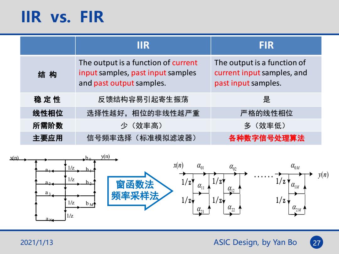
IIR vs.FIR IIR FIR The output is a function of current The output is a function of 结构 input samples,past input samples current input samples,and and past output samples. past input samples. 稳定性 反馈结构容易引起寄生振荡 是 线性相位 选择性越好,相位的非线性越严重 严格的线性相位 所需阶数 少(效率高) 多(效率低) 主要应用 信号频率选择(标准模拟滤波器) 各种数字信号处理算法 y(n) x(n Co CoM 1/2Y n 窗函数法 1/z 1/z a 频率采样法 1/2Y 1/2Y 1/2y 2021/1/13 ASIC Design,by Yan Bo 27
2021/1/13 ASIC Design, by Yan Bo 27 IIR vs. FIR IIR FIR 结 构 The output is a function of current input samples, past input samples and past output samples. The output is a function of current input samples, and past input samples. 稳 定 性 反馈结构容易引起寄生振荡 是 线性相位 选择性越好,相位的非线性越严重 严格的线性相位 所需阶数 少(效率高) 多(效率低) 主要应用 信号频率选择(标准模拟滤波器) 各种数字信号处理算法 1/z 1/z 1/z 1/z b 0 b 1 b 2 b M a 1 a 2 a 3 a N x(n) y(n) y(n) 1/z 1/z 1M 2M 1/z 1/z 12 22 1/z 1/z 11 21 01 02 0M ...... x(n) 窗函数法 频率采样法
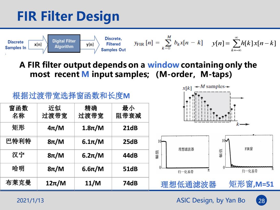
FIR Filter Design Discrete, M Discrete Digital Filter x[n] Samples In Algorithm y[n] Filtered aR网=∑bn-k个[]=∑]xn-个 Samples Out A FIR filter output depends on a window containing only the most recent M input samples;(M-order,M-taps) xk]←M samples-→ 根据过渡带宽选择窗函数和长度M 窗函数 近似 精确 最小 名称 过渡带宽 过渡带宽 阻带衰减 矩形 4π/M 1.8π/M 21dB 巴特利特 8π/M 6.1π/M 25dB 理想滤波器 FIR窗 汉宁 8π/M 6.2π/M 44dB 星 哈明 8π/M 6.6/M 51dB 归一化基带 归一化基带 布莱克曼 12/M 11/M 74dB 理想低通滤波器 矩形窗,M=51 2021/1/13 ASIC Design,by Yan Bo 28
ASIC Design, by Yan Bo A FIR filter output depends on a window containing only the most recent M input samples; (M-order,M-taps) =− = − k y[n] h[k] x[n k] 2021/1/13 28 FIR Filter Design 理想低通滤波器 矩形窗,M=51 窗函数 名称 近似 过渡带宽 精确 过渡带宽 最小 阻带衰减 矩形 4π/M 1.8π/M 21dB 巴特利特 8π/M 6.1π/M 25dB 汉宁 8π/M 6.2π/M 44dB 哈明 8π/M 6.6π/M 51dB 布莱克曼 12π/M 11/M 74dB 根据过渡带宽选择窗函数和长度M
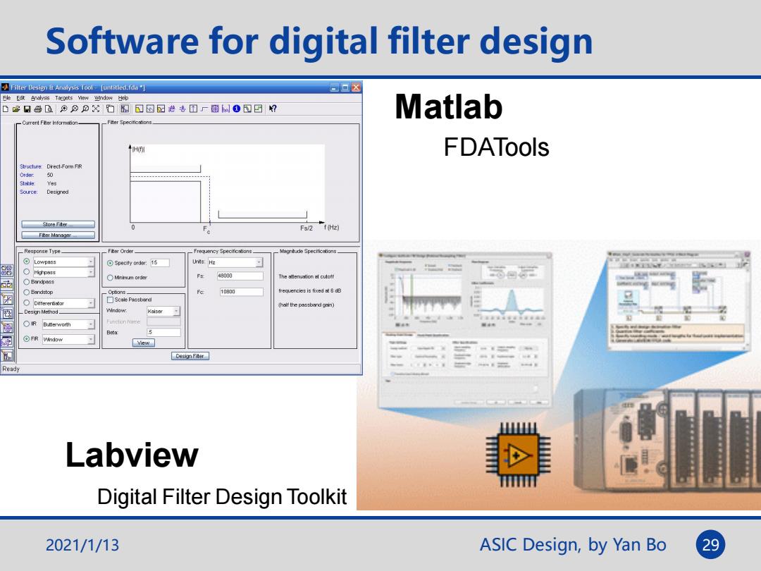
Software for digital filter design Filter Design Analysis Tool [untitled.fda"] 口▣☒ D3日色G知分公的图过因园#专四厂带制0)□? Matlab Current Fer Informstion FDATools Structure:Drect-Form FR Order 50 。 Yes Source: Store Fter Fs/2 (Hz) FEer Manager _Response Type F ter Order_ Frequency Specificstions. ⊙Lowpas Specity ordee:15 H 器 48000 The atenuation at cutoff OBn4中as Bandstop Ootions 10800 0 alt the passband gair) Window: 5 雨 ⊙FR wndow view Desi Fiter Ready Labview m Digital Filter Design Toolkit 2021/1/13 ASIC Design,by Yan Bo 29
ASIC Design, by Yan Bo Software for digital filter design 2021/1/13 29 Labview Digital Filter Design Toolkit Matlab FDATools
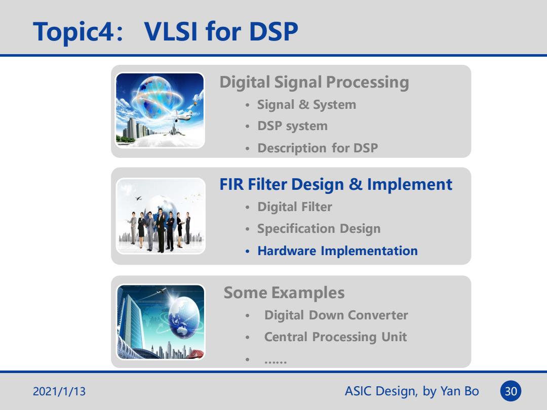
Topic4:VLSI for DSP Digital Signal Processing ·Signal&System 。DSP system ·Description for DSP FIR Filter Design Implement 。Digital Filter Specification Design Hardware Implementation Some Examples Digital Down Converter 。 Central Processing Unit h国 2021/1/13 ASIC Design,by Yan Bo 30
ASIC Design, by Yan Bo Topic4: VLSI for DSP Digital Signal Processing • Signal & System • DSP system • Description for DSP FIR Filter Design & Implement • Digital Filter • Specification Design • Hardware Implementation Some Examples • Digital Down Converter • Central Processing Unit • …… 2021/1/13 30
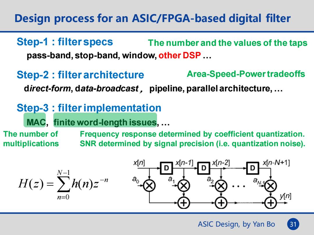
Design process for an ASIC/FPGA-based digital filter Step-1 filter specs The number and the values of the taps pass-band,stop-band,window,other DSP... Step-2:filter architecture Area-Speed-Power tradeoffs direct-form,data-broadcast,pipeline,parallel architecture,... Step-3:filter implementation MAC,finite word-length issues,... The number of Frequency response determined by coefficient quantization. multiplications SNR determined by signal precision(i.e.quantization noise). x(n] n- xn-2] X[n-N+1] W-1 He))=∑h(n)z" n=0 yn] ASIC Design,by Yan Bo 31
ASIC Design, by Yan Bo Design process for an ASIC/FPGA-based digital filter 31 Step-1 : filter specs pass-band, stop-band, window, other DSP … Step-2 : filter architecture direct-form, data-broadcast ,pipeline, parallel architecture, … Step-3 : filter implementation MAC, finite word-length issues, … Frequency response determined by coefficient quantization. SNR determined by signal precision (i.e. quantization noise). − = − = 1 0 ( ) ( ) N n n H z h n z Area-Speed-Power tradeoffs The number and the values of the taps The number of multiplications