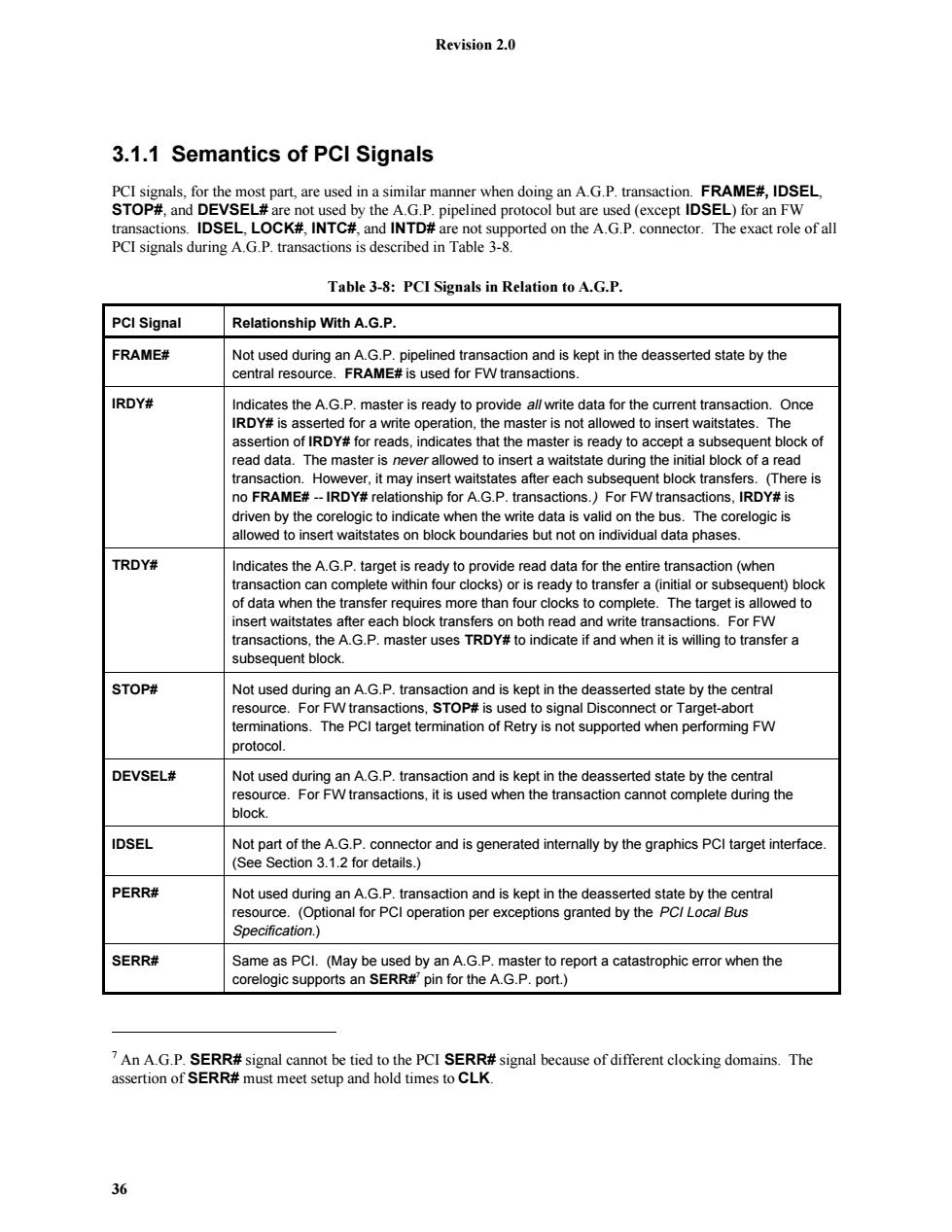
Revision 2.0 3.1.1 Semantics of PCI Signals PCI signals,for the most part,are used in a similar manner when doing an A.G.P.transaction.FRAME#,IDSEL, STOP#,and DEVSEL#are not used by the A.G.P.pipelined protocol but are used (except IDSEL)for an FW transactions.IDSEL,LOCK#,INTC#,and INTD#are not supported on the A.G.P.connector.The exact role of all PCI signals during A.G.P.transactions is described in Table 3-8. Table 3-8:PCI Signals in Relation to A.G.P. PCI Signal Relationship With A.G.P. FRAME# Not used during an A.G.P.pipelined transaction and is kept in the deasserted state by the central resource.FRAME#is used for FW transactions. IRDY# Indicates the A.G.P.master is ready to provide al/write data for the current transaction.Once IRDY#is asserted for a write operation,the master is not allowed to insert waitstates.The assertion of IRDY#for reads,indicates that the master is ready to accept a subsequent block of read data.The master is never allowed to insert a waitstate during the initial block of a read transaction.However,it may insert waitstates after each subsequent block transfers.(There is no FRAME#--IRDY#relationship for A.G.P.transactions.)For FW transactions,IRDY#is driven by the corelogic to indicate when the write data is valid on the bus.The corelogic is allowed to insert waitstates on block boundaries but not on individual data phases. TRDY# Indicates the A.G.P.target is ready to provide read data for the entire transaction(when transaction can complete within four clocks)or is ready to transfer a(initial or subsequent)block of data when the transfer requires more than four clocks to complete.The target is allowed to insert waitstates after each block transfers on both read and write transactions.For FW transactions,the A.G.P.master uses TRDY#to indicate if and when it is willing to transfer a subsequent block. STOP# Not used during an A.G.P.transaction and is kept in the deasserted state by the central resource.For FW transactions,STOP#is used to signal Disconnect or Target-abort terminations.The PCI target termination of Retry is not supported when performing FW protocol. DEVSEL# Not used during an A.G.P.transaction and is kept in the deasserted state by the central resource.For FW transactions,it is used when the transaction cannot complete during the block. IDSEL Not part of the A.G.P.connector and is generated internally by the graphics PCI target interface. (See Section 3.1.2 for details.) PERR# Not used during an A.G.P.transaction and is kept in the deasserted state by the central resource.(Optional for PCI operation per exceptions granted by the PC/Local Bus Specification.) SERR# Same as PCI.(May be used by an A.G.P.master to report a catastrophic error when the corelogic supports an SERR#'pin for the A.G.P.port.) 7 An A.G.P.SERR#signal cannot be tied to the PCI SERR#signal because of different clocking domains.The assertion of SERR#must meet setup and hold times to CLK. 36
Revision 2.0 36 3.1.1 Semantics of PCI Signals PCI signals, for the most part, are used in a similar manner when doing an A.G.P. transaction. FRAME#, IDSEL, STOP#, and DEVSEL# are not used by the A.G.P. pipelined protocol but are used (except IDSEL) for an FW transactions. IDSEL, LOCK#, INTC#, and INTD# are not supported on the A.G.P. connector. The exact role of all PCI signals during A.G.P. transactions is described in Table 3-8. Table 3-8: PCI Signals in Relation to A.G.P. PCI Signal Relationship With A.G.P. FRAME# Not used during an A.G.P. pipelined transaction and is kept in the deasserted state by the central resource. FRAME# is used for FW transactions. IRDY# Indicates the A.G.P. master is ready to provide all write data for the current transaction. Once IRDY# is asserted for a write operation, the master is not allowed to insert waitstates. The assertion of IRDY# for reads, indicates that the master is ready to accept a subsequent block of read data. The master is never allowed to insert a waitstate during the initial block of a read transaction. However, it may insert waitstates after each subsequent block transfers. (There is no FRAME# -- IRDY# relationship for A.G.P. transactions.) For FW transactions, IRDY# is driven by the corelogic to indicate when the write data is valid on the bus. The corelogic is allowed to insert waitstates on block boundaries but not on individual data phases. TRDY# Indicates the A.G.P. target is ready to provide read data for the entire transaction (when transaction can complete within four clocks) or is ready to transfer a (initial or subsequent) block of data when the transfer requires more than four clocks to complete. The target is allowed to insert waitstates after each block transfers on both read and write transactions. For FW transactions, the A.G.P. master uses TRDY# to indicate if and when it is willing to transfer a subsequent block. STOP# Not used during an A.G.P. transaction and is kept in the deasserted state by the central resource. For FW transactions, STOP# is used to signal Disconnect or Target-abort terminations. The PCI target termination of Retry is not supported when performing FW protocol. DEVSEL# Not used during an A.G.P. transaction and is kept in the deasserted state by the central resource. For FW transactions, it is used when the transaction cannot complete during the block. IDSEL Not part of the A.G.P. connector and is generated internally by the graphics PCI target interface. (See Section 3.1.2 for details.) PERR# Not used during an A.G.P. transaction and is kept in the deasserted state by the central resource. (Optional for PCI operation per exceptions granted by the PCI Local Bus Specification.) SERR# Same as PCI. (May be used by an A.G.P. master to report a catastrophic error when the corelogic supports an SERR#7 pin for the A.G.P. port.) 7 An A.G.P. SERR# signal cannot be tied to the PCI SERR# signal because of different clocking domains. The assertion of SERR# must meet setup and hold times to CLK

Revision 2.0 Table 3-8:PCI Signals in Relation to A.G.P.(continued) PCI Signal Relationship With A.G.P. REQ# Used to request access to the bus to initiate a PCI or an A.G.P.Request. GNT# Same meaning as PCI but additional information is provided on ST[2::0].The additional information indicates that the master is the recipient of previously requested read data(high or low priority),it is to provide write data(high or low priority)for a previously enqueued write command,or it has been given permission to start a bus transaction(A.G.P.or PCI). RST# Same as PCI. AD[31:00] Same as PCI. C/BE[3:0]# Slightly different meaning.Provides command information(different commands than PCI)from the master when requests are being enqueued using PIPE#.Provides valid byte information during A.G.P.write transactions and is driven by the master.The target drives to "0000"during the return of A.G.P.read data (in 1x and 2x modes)and is ignored by the A.G.P.master.In 4x mode,the byte enables are asserted for transfers that have valid data and deasserted for transfers that have meaningless data. PAR Not valid during an A.G.P.transaction,but must be actively driven by the current owner of the AD bus. LOCK# Is not supported on the A.G.P.interface for either A.G.P.or PCI transactions. INTA#,INTB# Interrupt request signalsare the same as PCI and follow the same usage.(Must be level sensitive and shareable.)INTA#for a single function device.INTB#for a two function device. INTC#and INTD#are not supported on the A.G.P.connector. Each signal can be required,optional,or not applicable,depending on the type of device(graphics or corelogic), which interface(PCI or A.G.P.)is supported,and the type of agent(master or target).Table 3-9 is a summary of the functionality supported by function and agent.Table 3-10 is a summary of the PCI signals supported by function and agent.Table 3-11 is a summary of the A.G.P.signals supported by function and agent.For example,the second column represents a graphics agent that supports the PCI interface as a target.The row labeled Support indicates whether the interface is required or optional.For the example,the PCI target interface is required by a graphics agent.The gray boxes indicate that the signal is not applicable to the function. Table 3-9:Summary of Interfaces Based on Function and Agent Device Graphics Corelogic Interface PCI A.G.P. PCI A.G.P. Agent Target Master Master FWTarget Target Master Target FW aster Support R 0 0 0 R R R 0 Legend: R Required 0 Optional 8 These can be tied to the PCI INTx#signals since these are o/d signals and are level sensitive.However,care must be taken to ensure electrical interface requirements are met.Refer to Section 4.3.4 for details. 37
Revision 2.0 37 Table 3-8: PCI Signals in Relation to A.G.P. (continued) PCI Signal Relationship With A.G.P. REQ# Used to request access to the bus to initiate a PCI or an A.G.P. Request. GNT# Same meaning as PCI but additional information is provided on ST[2::0]. The additional information indicates that the master is the recipient of previously requested read data (high or low priority), it is to provide write data (high or low priority) for a previously enqueued write command, or it has been given permission to start a bus transaction (A.G.P. or PCI). RST# Same as PCI. AD[31::00] Same as PCI. C/BE[3::0]# Slightly different meaning. Provides command information (different commands than PCI) from the master when requests are being enqueued using PIPE#. Provides valid byte information during A.G.P. write transactions and is driven by the master. The target drives to “0000” during the return of A.G.P. read data (in 1x and 2x modes) and is ignored by the A.G.P. master. In 4x mode, the byte enables are asserted for transfers that have valid data and deasserted for transfers that have meaningless data. PAR Not valid during an A.G.P. transaction, but must be actively driven by the current owner of the AD bus. LOCK# Is not supported on the A.G.P. interface for either A.G.P. or PCI transactions. INTA#, INTB# Interrupt request signals8 are the same as PCI and follow the same usage. (Must be level sensitive and shareable.) INTA# for a single function device, INTB# for a two function device. INTC# and INTD# are not supported on the A.G.P. connector. Each signal can be required, optional, or not applicable, depending on the type of device (graphics or corelogic), which interface (PCI or A.G.P.) is supported, and the type of agent (master or target). Table 3-9 is a summary of the functionality supported by function and agent. Table 3-10 is a summary of the PCI signals supported by function and agent. Table 3-11 is a summary of the A.G.P. signals supported by function and agent. For example, the second column represents a graphics agent that supports the PCI interface as a target. The row labeled Support indicates whether the interface is required or optional. For the example, the PCI target interface is required by a graphics agent. The gray boxes indicate that the signal is not applicable to the function. Table 3-9: Summary of Interfaces Based on Function and Agent Device Graphics Corelogic Interface PCI A.G.P. PCI A.G.P. Agent Target Master Master FWTarget Target Master Target FWMaster Support ROOORRRO Legend: R Required O Optional 8 These can be tied to the PCI INTx# signals since these are o/d signals and are level sensitive. However, care must be taken to ensure electrical interface requirements are met. Refer to Section 4.3.4 for details
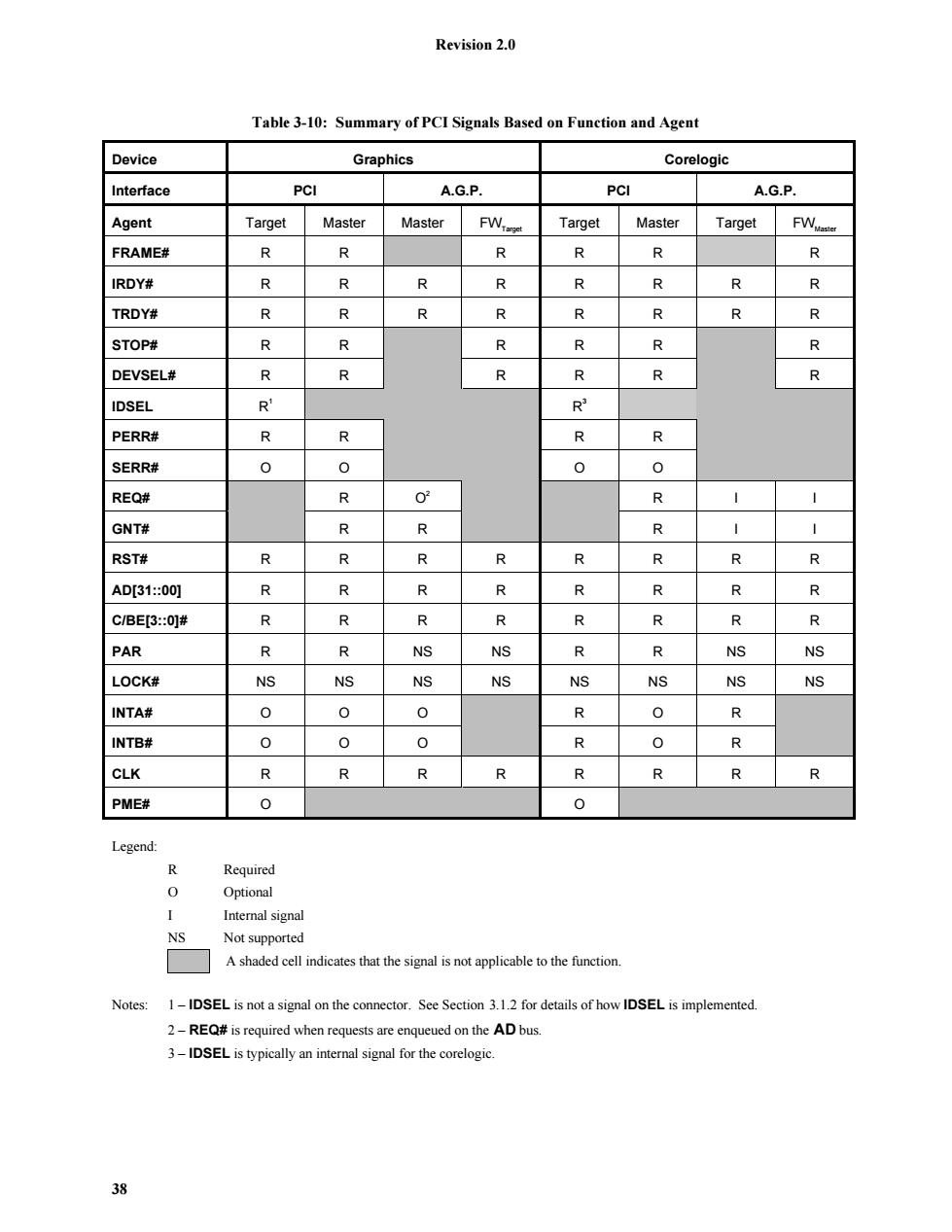
Revision 2.0 Table 3-10:Summary of PCI Signals Based on Function and Agent Device Graphics Corelogic Interface PCI A.G.P. PCI A.G.P. Agent Target Master Master FWTanget Target Master Target FW aster FRAME# R R R R R 尽 IRDY# R R R R R R R R TRDY# R R R R R R R R STOP# R R R R R 个 DEVSEL# R R R R R R IDSEL R R PERR# R R R R SERR# 0 0 0 0 REQ# 个 02 个 GNT# 个 R R RST# R R R R R R R R AD[31:00] R 个 个 个 R R R R C/BE[3:0]# R R 个 R R R R 个 PAR R R NS NS R R NS NS LOCK# NS NS NS NS NS NS NS NS INTA# 0 0 0 R 0 R INTB# 0 0 0 R 0 R CLK R R R R R R R R PME# 0 0 Legend: R Required 0 Optional Internal signal NS Not supported A shaded cell indicates that the signal is not applicable to the function. Notes: 1-IDSEL is not a signal on the connector.See Section 3.1.2 for details of how IDSEL is implemented. 2-REQ#is required when requests are enqueued on the AD bus. 3-IDSEL is typically an internal signal for the corelogic. 38
Revision 2.0 38 Table 3-10: Summary of PCI Signals Based on Function and Agent Device Graphics Corelogic Interface PCI A.G.P. PCI A.G.P. Agent Target Master Master FWTarget Target Master Target FWMaster FRAME# R R RRR R IRDY# RRRRRRRR TRDY# RRRRRRRR STOP# R R RRR R DEVSEL# R R RRR R IDSEL R1 R3 PERR# R R R R SERR# O O O O REQ# R O2 RI I GNT# R R RI I RST# RRRRRRRR AD[31::00] RRRRRRRR C/BE[3::0]# RRRRRRRR PAR R R NS NS R R NS NS LOCK# NS NS NS NS NS NS NS NS INTA# OOO ROR INTB# OOO ROR CLK RRRRRRRR PME# O O Legend: R Required O Optional I Internal signal NS Not supported A shaded cell indicates that the signal is not applicable to the function. Notes: 1 – IDSEL is not a signal on the connector. See Section 3.1.2 for details of how IDSEL is implemented. 2 – REQ# is required when requests are enqueued on the AD bus. 3 – IDSEL is typically an internal signal for the corelogic
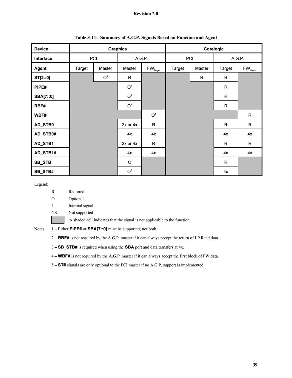
Revision 2.0 Table 3-11:Summary of A.G.P.Signals Based on Function and Agent Device Graphics Corelogic Interface PCI A.G.P. PCI A.G.P. Agent Target Master Master FW-anget Target Master Target FWamter ST[2:0] 0 R R R PIPE# 0' R SBA[7::0] 0 个 RBF# 02 R WBF# 0 R AD_STBO 2x or 4x R R 个 AD_STBO# 4x 4x 4x 4x AD_STB1 2x or 4x R 个 R AD_STB1# 4x 4x 4x 4x SB_STB 0 R SB_STB# 03 4x Legend: R Required 0 Optional Internal signal NS Not supported A shaded cell indicates that the signal is not applicable to the function. Notes:1-Either PIPE#or SBA[7::0]must be supported;not both. 2-RBF#is not required by the A.G.P.master if it can always accept the return of LP Read data. 3-SB_STB#is required when using the SBA port and data transfers at 4x. 4-WBF#is not required by the A.G.P.master if it can always accept the first block of FW data. 5-ST#signals are only optional to the PCI master if no A.G.P.support is implemented. 39
Revision 2.0 39 Table 3-11: Summary of A.G.P. Signals Based on Function and Agent Device Graphics Corelogic Interface PCI A.G.P. PCI A.G.P. Agent Target Master Master FWTarget Target Master Target FWMaster ST[2::0] O5 R R R PIPE# O1 R SBA[7::0] O1 R RBF# O2 R WBF# O4 R AD_STB0 2x or 4x R R R AD_STB0# 4x 4x 4x 4x AD_STB1 2x or 4x R R R AD_STB1# 4x 4x 4x 4x SB_STB O R SB_STB# O3 4x Legend: R Required O Optional I Internal signal NS Not supported A shaded cell indicates that the signal is not applicable to the function. Notes: 1 – Either PIPE# or SBA[7::0] must be supported; not both. 2 – RBF# is not required by the A.G.P. master if it can always accept the return of LP Read data. 3 – SB_STB# is required when using the SBA port and data transfers at 4x. 4 – WBF# is not required by the A.G.P. master if it can always accept the first block of FW data. 5 – ST# signals are only optional to the PCI master if no A.G.P. support is implemented
Revision 2.0 3.1.2 Configuration of an A.G.P.Master Initialization of an A.G.P.device is done via the configuration mechanism defined by the PCI Local Bus Specification.This interface specification does not define a new mechanism.An A.G.P.master is composed of a PCI target interface and an A.G.P.master interface.(Optionally,the device can also include a PCI master interface when required.)The PCI target interface follows the PC/Local Bus Specification.This requires the device to respond to a PCI configuration transaction when a configuration command (read or write)is decoded and AD01 and AD00 are both"0"and the device's IDSEL is asserted.Since IDSEL is not a signal in the A.G.P.connector,it must be connected to AD16 at the component.The designer of the A.G.P.master must be careful as to how this connection is made.It must be connected internally for A.G.P.operation while it must be connected externally for PCI operation.The next two sections will describe how this connection must be made based on the targeted market segment of the device. 3.1.2.1 Device for A.G.P.Only Operation When the device is designed for exclusive operation on the A.G.P.interface,the device does not have an external IDSEL pin.In this implementation,the device asserts DEVSEL#when the bus command is configuration(read or write).AD16 is a"1"while AD1 and ADO are"00".Under all other conditions,the device's configuration space has not been selected and the device does not assert DEVSEL#to claim the access.System software will scan all configuration spaces supported by asserting a different AD signal between AD16 and AD31 while performing a PCI configuration read or write command.A device located on that segment can only assert DEVSEL#for a single configuration space which is uniquely identified by having its IDSEL asserted when AD1-0 are"00".The exception is for a multi-function device that has bit 7 of the header type field set.In this case,the different functions are selected based on the function number decoded (AD10-AD8).See the PCI Local Bus Specification for more details. 3.1.2.2 Device for Both PCI and A.G.P.Operation When a device is designed to be used on both A.G.P.and PCI bus segments,then the device needs to have two modes of operation.When in the A.G.P.mode,the device generates DEVSEL#as described in the A.G.P.only implementation.When used in a PCI mode of operation,the device must provide an external IDSEL that is connected to one of the AD signals.Which AD signal it is connected to is determined by the system designer and NOT by the component designer.In this case,the device must be"strapped"to indicate which mode it is operating in.Note:that besides how DEVSEL#is generated during configuration accesses,the device must also know the strength in which it drives its output buffers.Note:A.G.P.requires only half the strength of a PCI buffer,since A.G.P.is a point-to-point connection and not a bus environment like PCI. Refers to the condition where information is conveyed to the device by sampling a pin to determine how the device should behave.For example,if the pin is tied to Vcc the device supports mode X,otherwise it supports mode Y. 40
Revision 2.0 40 3.1.2 Configuration of an A.G.P. Master Initialization of an A.G.P. device is done via the configuration mechanism defined by the PCI Local Bus Specification. This interface specification does not define a new mechanism. An A.G.P. master is composed of a PCI target interface and an A.G.P. master interface. (Optionally, the device can also include a PCI master interface when required.) The PCI target interface follows the PCI Local Bus Specification. This requires the device to respond to a PCI configuration transaction when a configuration command (read or write) is decoded and AD01 and AD00 are both “0” and the device’s IDSEL is asserted. Since IDSEL is not a signal in the A.G.P. connector, it must be connected to AD16 at the component. The designer of the A.G.P. master must be careful as to how this connection is made. It must be connected internally for A.G.P. operation while it must be connected externally for PCI operation. The next two sections will describe how this connection must be made based on the targeted market segment of the device. 3.1.2.1 Device for A.G.P. Only Operation When the device is designed for exclusive operation on the A.G.P. interface, the device does not have an external IDSEL pin. In this implementation, the device asserts DEVSEL# when the bus command is configuration (read or write). AD16 is a “1” while AD1 and AD0 are “00”. Under all other conditions, the device’s configuration space has not been selected and the device does not assert DEVSEL# to claim the access. System software will scan all configuration spaces supported by asserting a different AD signal between AD16 and AD31 while performing a PCI configuration read or write command. A device located on that segment can only assert DEVSEL# for a single configuration space which is uniquely identified by having its IDSEL asserted when AD1-0 are “00”. The exception is for a multi-function device that has bit 7 of the header type field set. In this case, the different functions are selected based on the function number decoded (AD10-AD8). See the PCI Local Bus Specification for more details. 3.1.2.2 Device for Both PCI and A.G.P. Operation When a device is designed to be used on both A.G.P. and PCI bus segments, then the device needs to have two modes of operation. When in the A.G.P. mode, the device generates DEVSEL# as described in the A.G.P. only implementation. When used in a PCI mode of operation, the device must provide an external IDSEL that is connected to one of the AD signals. Which AD signal it is connected to is determined by the system designer and NOT by the component designer. In this case, the device must be “strapped”9 to indicate which mode it is operating in. Note: that besides how DEVSEL# is generated during configuration accesses, the device must also know the strength in which it drives its output buffers. Note: A.G.P. requires only half the strength of a PCI buffer, since A.G.P. is a point-to-point connection and not a bus environment like PCI. 9 Refers to the condition where information is conveyed to the device by sampling a pin to determine how the device should behave. For example, if the pin is tied to Vcc the device supports mode X, otherwise it supports mode Y