JEDEC DESIGN STANDARD DESIGN REQUIREMENTS FOR OUTLINES OF SOLID STATE AND RELATED PRODUCTS JEDEC PUBLICATION 95 Design Guide 4.21 INTERNAL STACKING MODULE,LAND GRID ARRAY PACKAGES WITH EXTERNAL INTERCONNECT TERMINALS (ISM) JEDEC SOLID STATE TECHNOLOGY ASSOCIATION Date:March 2007 Issue:A Item:11.2-699(s)
JEDEC DESIGN STANDARD DESIGN REQUIREMENTS FOR OUTLINES OF SOLID STATE AND RELATED PRODUCTS JEDEC PUBLICATION 95 Design Guide 4.21 INTERNAL STACKING MODULE, LAND GRID ARRAY PACKAGES WITH EXTERNAL INTERCONNECT TERMINALS (ISM) _______________________________________ _______________________________________ JEDEC SOLID STATE TECHNOLOGY ASSOCIATION Date: March 2007 Issue: A Item: 11.2-699(S)
JEDEC PUBLICATION 95 PAGE 4.21-1/A INTERNAL STACKING MODULE,LAND GRID ARRAY PACKAGES WITH EXTERNAL INTERCONNECT TERMINALS (ISM) Contents Sections Pages 4.21 Scope 4.21-2 4.21.1 Illustrations 4.21-2 4.21.2 Package Description 4.21-3 4.21.3 Concept 4.21-4 4.21.4 Recommended Package Outline 4.21-4 4.21.5 Recommended Values and Tolerances 4.21-4 4.21.6 Notes 4.21-12 Tables 4.21-1 Symbols,Recommended Values and Tolerances 4.21-5 Figures 4.21-1 Internal Stacking Module Land Grid Array Packages with 4.21-2 External Interconnect Terminals 4.21-2 ISM LGA Package Stacked within another Package 4.21-3 4.21-3 ISM Top,Side,and Bottom Views 4.21-9 4.21-4 Side View Detail 4.21-10 4.21-5 Bond Finger Terminal Detail 4.21-11
JEDEC PUBLICATION 95 PAGE 4.21-1/A INTERNAL STACKING MODULE, LAND GRID ARRAY PACKAGES WITH EXTERNAL INTERCONNECT TERMINALS (ISM) Contents Sections Pages 4.21 Scope 4.21-2 4.21.1 Illustrations 4.21-2 4.21.2 Package Description 4.21-3 4.21.3 Concept 4.21-4 4.21.4 Recommended Package Outline 4.21-4 4.21.5 Recommended Values and Tolerances 4.21-4 4.21.6 Notes 4.21-12 Tables 4.21-1 Symbols, Recommended Values and Tolerances 4.21-5 Figures 4.21-1 Internal Stacking Module Land Grid Array Packages with 4.21-2 External Interconnect Terminals 4.21-2 ISM LGA Package Stacked within another Package 4.21-3 4.21-3 ISM Top, Side, and Bottom Views 4.21-9 4.21-4 Side View Detail 4.21-10 4.21-5 Bond Finger Terminal Detail 4.21-11
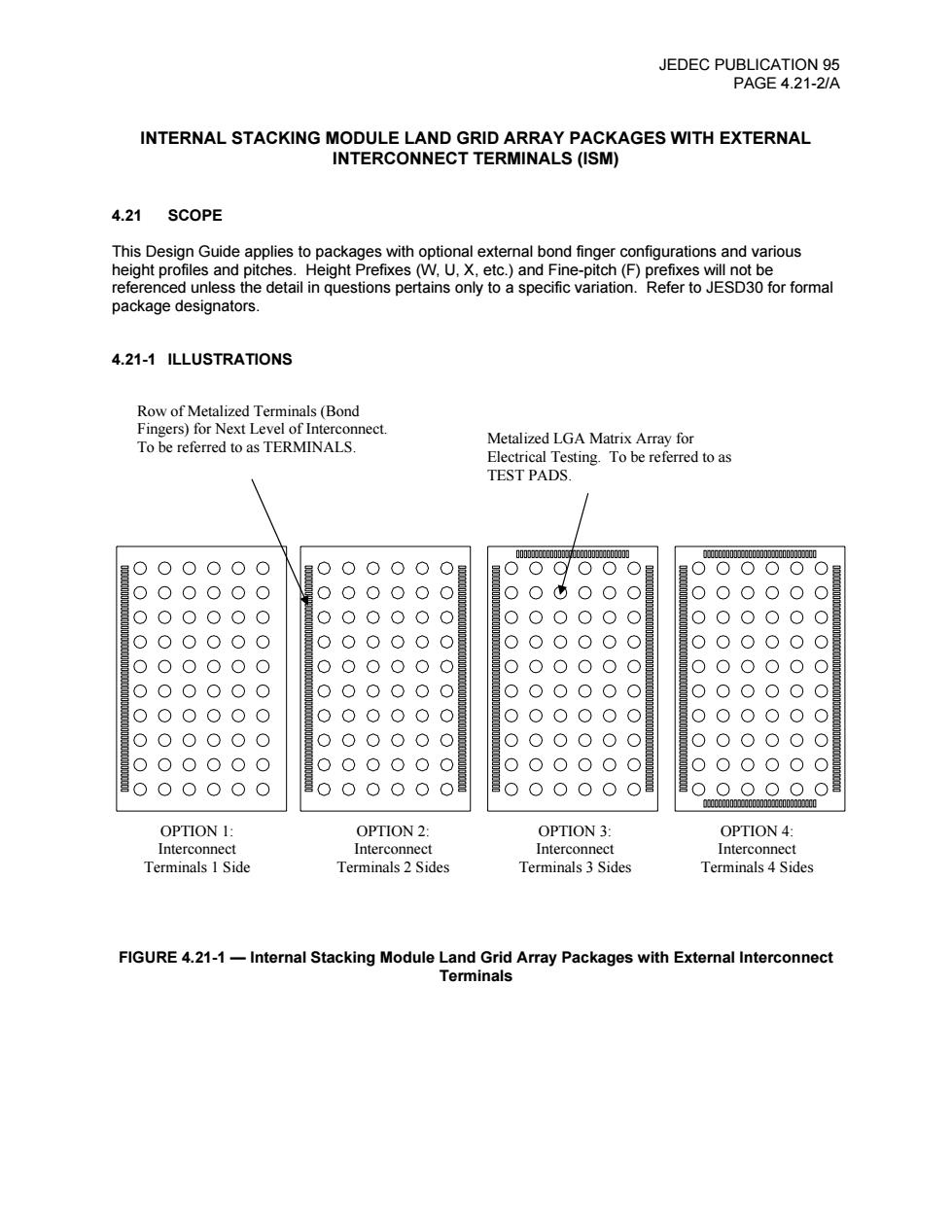
JEDEC PUBLICATION 95 PAGE 4.21-2/A INTERNAL STACKING MODULE LAND GRID ARRAY PACKAGES WITH EXTERNAL INTERCONNECT TERMINALS (ISM) 4.21 SCOPE This Design Guide applies to packages with optional external bond finger configurations and various height profiles and pitches.Height Prefixes(W,U,X,etc.)and Fine-pitch(F)prefixes will not be referenced unless the detail in questions pertains only to a specific variation.Refer to JESD30 for formal package designators. 4.21-1 ILLUSTRATIONS Row of Metalized Terminals(Bond Fingers)for Next Level of Interconnect. To be referred to as TERMINALS. Metalized LGA Matrix Array for Electrical Testing.To be referred to as TEST PADS 00加u100中.0000加1.000加J a.0000010000011000uJ0 0○○ O ● 0000000000000000000000 OPTION 1: OPTION 2: OPTION 3: OPTION 4: Interconnect Interconnect Interconnect Interconnect Terminals 1 Side Terminals 2 Sides Terminals 3 Sides Terminals 4 Sides FIGURE 4.21-1-Internal Stacking Module Land Grid Array Packages with External Interconnect Terminals
JEDEC PUBLICATION 95 PAGE 4.21-2/A INTERNAL STACKING MODULE LAND GRID ARRAY PACKAGES WITH EXTERNAL INTERCONNECT TERMINALS (ISM) 4.21 SCOPE This Design Guide applies to packages with optional external bond finger configurations and various height profiles and pitches. Height Prefixes (W, U, X, etc.) and Fine-pitch (F) prefixes will not be referenced unless the detail in questions pertains only to a specific variation. Refer to JESD30 for formal package designators. 4.21-1 ILLUSTRATIONS FIGURE 4.21-1 — Internal Stacking Module Land Grid Array Packages with External Interconnect Terminals Metalized LGA Matrix Array for Electrical Testing. To be referred to as TEST PADS. Row of Metalized Terminals (Bond Fingers) for Next Level of Interconnect. To be referred to as TERMINALS. OPTION 1: Interconnect Terminals 1 Side OPTION 2: Interconnect Terminals 2 Sides OPTION 3: Interconnect Terminals 3 Sides OPTION 4: Interconnect Terminals 4 Sides
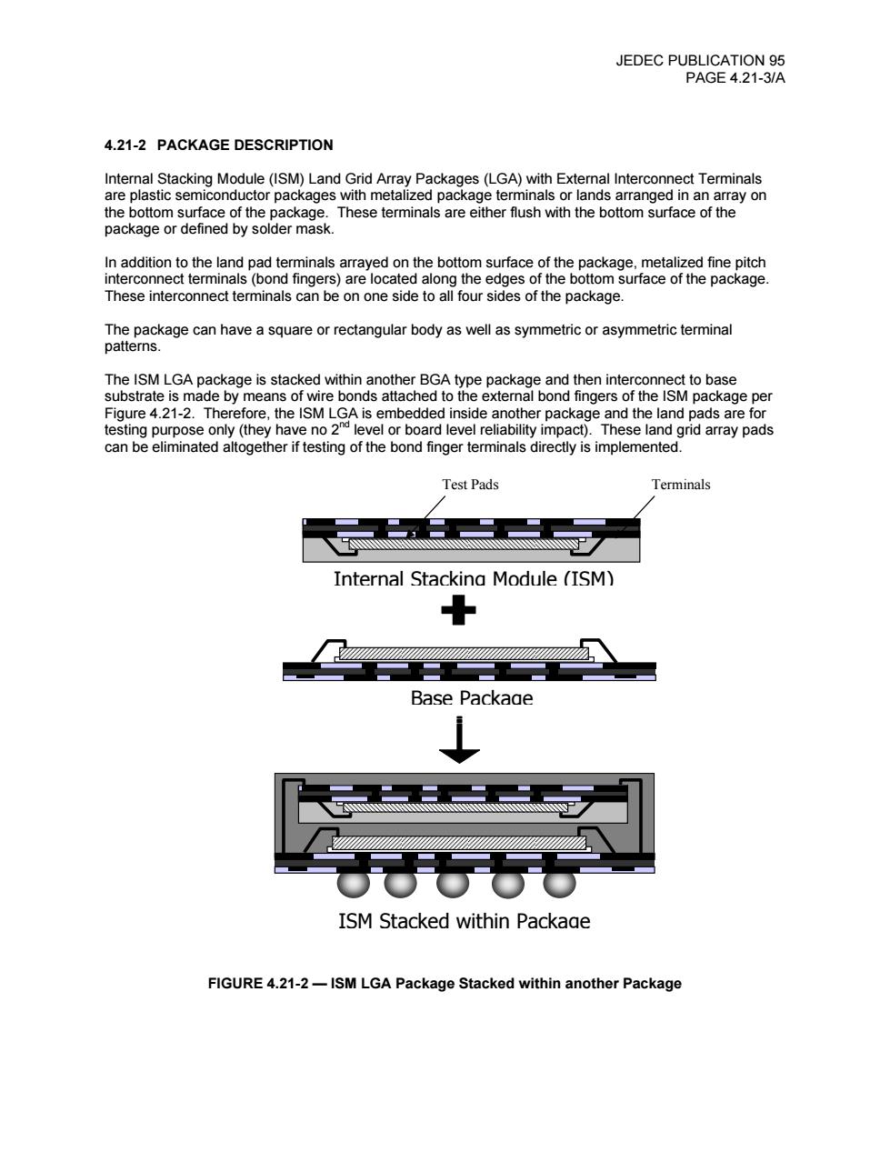
JEDEC PUBLICATION 95 PAGE 4.21-3/A 4.21-2 PACKAGE DESCRIPTION Internal Stacking Module(ISM)Land Grid Array Packages(LGA)with External Interconnect Terminals are plastic semiconductor packages with metalized package terminals or lands arranged in an array on the bottom surface of the package.These terminals are either flush with the bottom surface of the package or defined by solder mask. In addition to the land pad terminals arrayed on the bottom surface of the package,metalized fine pitch interconnect terminals(bond fingers)are located along the edges of the bottom surface of the package. These interconnect terminals can be on one side to all four sides of the package. The package can have a square or rectangular body as well as symmetric or asymmetric terminal patterns. The ISM LGA package is stacked within another BGA type package and then interconnect to base substrate is made by means of wire bonds attached to the external bond fingers of the ISM package per Figure 4.21-2.Therefore,the ISM LGA is embedded inside another package and the land pads are for testing purpose only(they have no 2 level or board level reliability impact).These land grid array pads can be eliminated altogether if testing of the bond finger terminals directly is implemented. Test Pads Terminals AW. Internal Stackina Module (ISM) Base Packaae ISM Stacked within Package FIGURE 4.21-2-ISM LGA Package Stacked within another Package
JEDEC PUBLICATION 95 PAGE 4.21-3/A 4.21-2 PACKAGE DESCRIPTION Internal Stacking Module (ISM) Land Grid Array Packages (LGA) with External Interconnect Terminals are plastic semiconductor packages with metalized package terminals or lands arranged in an array on the bottom surface of the package. These terminals are either flush with the bottom surface of the package or defined by solder mask. In addition to the land pad terminals arrayed on the bottom surface of the package, metalized fine pitch interconnect terminals (bond fingers) are located along the edges of the bottom surface of the package. These interconnect terminals can be on one side to all four sides of the package. The package can have a square or rectangular body as well as symmetric or asymmetric terminal patterns. The ISM LGA package is stacked within another BGA type package and then interconnect to base substrate is made by means of wire bonds attached to the external bond fingers of the ISM package per Figure 4.21-2. Therefore, the ISM LGA is embedded inside another package and the land pads are for testing purpose only (they have no 2nd level or board level reliability impact). These land grid array pads can be eliminated altogether if testing of the bond finger terminals directly is implemented. FIGURE 4.21-2 — ISM LGA Package Stacked within another Package Internal Stacking Module (ISM) ISM Stacked within Package Base Package Test Pads Terminals
JEDEC PUBLICATION 95 PAGE 4.21-4/A 4.21-3 CONCEPT This design guide defines the symbology,algorithms,dimensions and tolerances for ISM LGA packages with external bond fingers.The guidelines are based on metric dimensions and adhere to the geometric dimensioning and tolerancing principles defined in ASME Y14.5M-1994. 4.21-4 RECOMMENDED PACKAGE OUTLINE Refer to Table 4.21-1 and Figures 4.21-3 though 4.21-5 for the recommended symbology and outline format for ISM LGA packages. 4.21-5 RECOMMENDED VALUES AND TOLERANCES The following table defines the symbology and recommended algorithms,dimensions and tolerances that shall be used when preparing an ISM LGA package outline
JEDEC PUBLICATION 95 PAGE 4.21-4/A 4.21-3 CONCEPT This design guide defines the symbology, algorithms, dimensions and tolerances for ISM LGA packages with external bond fingers. The guidelines are based on metric dimensions and adhere to the geometric dimensioning and tolerancing principles defined in ASME Y14.5M-1994. 4.21-4 RECOMMENDED PACKAGE OUTLINE Refer to Table 4.21-1 and Figures 4.21-3 though 4.21-5 for the recommended symbology and outline format for ISM LGA packages. 4.21-5 RECOMMENDED VALUES AND TOLERANCES The following table defines the symbology and recommended algorithms, dimensions and tolerances that shall be used when preparing an ISM LGA package outline