Revision 2.0 1.3 Terminology This revision of the A.G.P.interface specification refers to various devices that are compatible with the A.G.P. interface (for example,masters and targets).The A.G.P.Interface Specification,Revision 1.0 refers to such devices as A.G.P.-compliant devices or A.G.P.-enabled devices(for example,A.G.P.-compliant masters,A.G.P.-compliant targets,and A.G.P.-enabled masters).This revision of the interface specification simplifies this terminology by using terms such as A.G.P.device,A.G.P.master,and A.G.P.target to refer to devices that are compatible with the A.G.P. interface specification. 21
Revision 2.0 21 1.3 Terminology This revision of the A.G.P. interface specification refers to various devices that are compatible with the A.G.P. interface (for example, masters and targets). The A.G.P. Interface Specification, Revision 1.0 refers to such devices as A.G.P.-compliant devices or A.G.P.-enabled devices (for example, A.G.P.-compliant masters, A.G.P.-compliant targets, and A.G.P.-enabled masters). This revision of the interface specification simplifies this terminology by using terms such as A.G.P. device, A.G.P. master, and A.G.P. target to refer to devices that are compatible with the A.G.P. interface specification

Revision 2.0 2.Architectural Context and Scope This chapter provides an architectural context for the actual specification of the Accelerated Graphics Port(A.G.P. or AGP)interface,hopefully motivating the design and making details easier to understand.It also is intended to set the technical scope of the interface specification in some areas by providing examples of issues beyond the purview of the formal interface specification. 2.1 Two Usage Models:“Execute”and“DMA” There are two primary A.G.P.usage models for 3D rendering that have to do with how data are partitioned and accessed,and the resultant interface data flow characteristics.In the"DMA"model,the primary graphics memory is the local memory associated with the accelerator,referred to as"local frame buffer".3D structures are stored in system memory,but are not used (or"executed")directly from this memory;rather they are copied to primary (local) memory (the"DMA"operation)to which the rendering engine's address generator makes its references.This implies that the traffic on the A.G.P.tends to be long,sequential transfers,serving the purpose of bulk data transport from system memory to primary graphics(local)memory.This sort of access model is amenable to a linked list of physical addresses provided by software(similar to operation of a disk or network I/O device),and is generally not sensitive to a non-contiguous view of the memory space. In the "execute"model,the accelerator uses both the local memory and the system memory as primary graphics memory.From the accelerator's perspective,the two memory systems are logically equivalent;any data structure may be allocated in either memory,with performance optimization as the only criteria for selection.In general, structures in system memory space are not copied into the local memory prior to use by the accelerator,but are "executed"in place.This implies that the traffic on the A.G.P.tends to be short,random accesses,which are not amenable to an access model based on software resolved lists of physical addresses.Because the accelerator generates direct references into system memory,a contiguous view of that space is essential;however,since system memory is dynamically allocated in random 4K pages,it is necessary in the "execute"model to provide an address mapping mechanism that maps random 4K pages into a single contiguous,physical address space. The A.G.P.supports both the"DMA"and"execute"models.However,since a primary motivation of the A.G.P.is to reduce growth pressure on local memory,the"execute"model is the design center.Consistent with that emphasis, this interface specification requires a physical-to-physical address remapping mechanism which insures the graphics accelerator(an A.G.P.master)will have a contiguous view of graphics data structures dynamically allocated in system memory. 23
Revision 2.0 23 This chapter provides an architectural context for the actual specification of the Accelerated Graphics Port (A.G.P. or AGP) interface, hopefully motivating the design and making details easier to understand. It also is intended to set the technical scope of the interface specification in some areas by providing examples of issues beyond the purview of the formal interface specification. 2.1 Two Usage Models: “Execute” and “DMA” There are two primary A.G.P. usage models for 3D rendering that have to do with how data are partitioned and accessed, and the resultant interface data flow characteristics. In the “DMA” model, the primary graphics memory is the local memory associated with the accelerator, referred to as “local frame buffer”. 3D structures are stored in system memory, but are not used (or “executed”) directly from this memory; rather they are copied to primary (local) memory (the “DMA” operation) to which the rendering engine’s address generator makes its references. This implies that the traffic on the A.G.P. tends to be long, sequential transfers, serving the purpose of bulk data transport from system memory to primary graphics (local) memory. This sort of access model is amenable to a linked list of physical addresses provided by software (similar to operation of a disk or network I/O device), and is generally not sensitive to a non-contiguous view of the memory space. In the “execute” model, the accelerator uses both the local memory and the system memory as primary graphics memory. From the accelerator’s perspective, the two memory systems are logically equivalent; any data structure may be allocated in either memory, with performance optimization as the only criteria for selection. In general, structures in system memory space are not copied into the local memory prior to use by the accelerator, but are “executed” in place. This implies that the traffic on the A.G.P. tends to be short, random accesses, which are not amenable to an access model based on software resolved lists of physical addresses. Because the accelerator generates direct references into system memory, a contiguous view of that space is essential; however, since system memory is dynamically allocated in random 4K pages, it is necessary in the “execute” model to provide an address mapping mechanism that maps random 4K pages into a single contiguous, physical address space. The A.G.P. supports both the “DMA” and “execute” models. However, since a primary motivation of the A.G.P. is to reduce growth pressure on local memory, the “execute” model is the design center. Consistent with that emphasis, this interface specification requires a physical-to-physical address remapping mechanism which insures the graphics accelerator (an A.G.P. master) will have a contiguous view of graphics data structures dynamically allocated in system memory. 2. Architectural Context and Scope
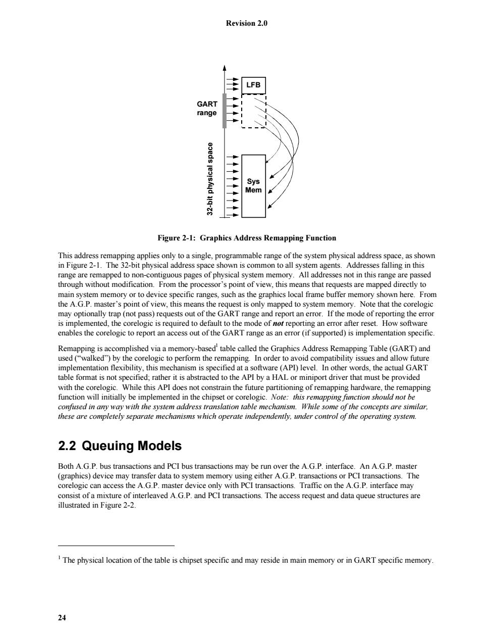
Revision 2.0 LFB GART range Sys Mem Figure 2-1:Graphics Address Remapping Function This address remapping applies only to a single,programmable range of the system physical address space,as shown in Figure 2-1.The 32-bit physical address space shown is common to all system agents.Addresses falling in this range are remapped to non-contiguous pages of physical system memory.All addresses not in this range are passed through without modification.From the processor's point of view,this means that requests are mapped directly to main system memory or to device specific ranges,such as the graphics local frame buffer memory shown here.From the A.G.P.master's point of view,this means the request is only mapped to system memory.Note that the corelogic may optionally trap(not pass)requests out of the GART range and report an error.If the mode of reporting the error is implemented,the corelogic is required to default to the mode of not reporting an error after reset.How software enables the corelogic to report an access out of the GART range as an error(if supported)is implementation specific. Remapping is accomplished via a memory-based'table called the Graphics Address Remapping Table(GART)and used("walked")by the corelogic to perform the remapping.In order to avoid compatibility issues and allow future implementation flexibility,this mechanism is specified at a software(APl)level.In other words,the actual GART table format is not specified;rather it is abstracted to the API by a HAL or miniport driver that must be provided with the corelogic.While this API does not constrain the future partitioning of remapping hardware,the remapping function will initially be implemented in the chipset or corelogic.Note:this remapping function should not be confused in any way with the system address translation table mechanism.While some of the concepts are similar, these are completely separate mechanisms which operate independently,under control of the operating system. 2.2 Queuing Models Both A.G.P.bus transactions and PCI bus transactions may be run over the A.G.P.interface.An A.G.P.master (graphics)device may transfer data to system memory using either A.G.P.transactions or PCI transactions.The corelogic can access the A.G.P.master device only with PCI transactions.Traffic on the A.G.P.interface may consist of a mixture of interleaved A.G.P.and PCI transactions.The access request and data queue structures are illustrated in Figure 2-2. 1 The physical location of the table is chipset specific and may reside in main memory or in GART specific memory. 24
Revision 2.0 24 LFB Sys Mem 32-bit physical space GART range Figure 2-1: Graphics Address Remapping Function This address remapping applies only to a single, programmable range of the system physical address space, as shown in Figure 2-1. The 32-bit physical address space shown is common to all system agents. Addresses falling in this range are remapped to non-contiguous pages of physical system memory. All addresses not in this range are passed through without modification. From the processor’s point of view, this means that requests are mapped directly to main system memory or to device specific ranges, such as the graphics local frame buffer memory shown here. From the A.G.P. master’s point of view, this means the request is only mapped to system memory. Note that the corelogic may optionally trap (not pass) requests out of the GART range and report an error. If the mode of reporting the error is implemented, the corelogic is required to default to the mode of not reporting an error after reset. How software enables the corelogic to report an access out of the GART range as an error (if supported) is implementation specific. Remapping is accomplished via a memory-based1 table called the Graphics Address Remapping Table (GART) and used (“walked”) by the corelogic to perform the remapping. In order to avoid compatibility issues and allow future implementation flexibility, this mechanism is specified at a software (API) level. In other words, the actual GART table format is not specified; rather it is abstracted to the API by a HAL or miniport driver that must be provided with the corelogic. While this API does not constrain the future partitioning of remapping hardware, the remapping function will initially be implemented in the chipset or corelogic. Note: this remapping function should not be confused in any way with the system address translation table mechanism. While some of the concepts are similar, these are completely separate mechanisms which operate independently, under control of the operating system. 2.2 Queuing Models Both A.G.P. bus transactions and PCI bus transactions may be run over the A.G.P. interface. An A.G.P. master (graphics) device may transfer data to system memory using either A.G.P. transactions or PCI transactions. The corelogic can access the A.G.P. master device only with PCI transactions. Traffic on the A.G.P. interface may consist of a mixture of interleaved A.G.P. and PCI transactions. The access request and data queue structures are illustrated in Figure 2-2. 1 The physical location of the table is chipset specific and may reside in main memory or in GART specific memory
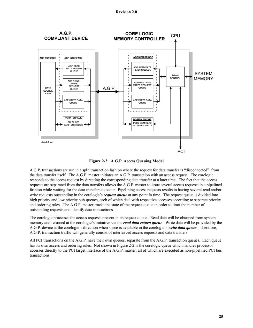
Revision 2.0 A.G.P. CORE LOGIC COMPLIANT DEVICE CPU MEMORY CONTROLLER AGP FUNCTION AGP INTERFACE AGP/MEM BRIDGE A2P只EA门 DATA RETURN AGP READ DATA QUEUE RETURN QUEUE ·:; DRAM SYSTEM 物 CONTROL MEMORY AGP READ/ WRITE AGP READ AND 物 REQUEST WRITE REQUEST DATA QUEUE SOURCE QUEUE A.G.P /SINK AGP WRITE DATA AGP WRITE DATA QUEUE QUEUE PCI INTERFACE PCIMEM BRIDGE PCI SLAVE (MASTER optional) PCI to MEM READ PCI Io MEM WRITE datanlo2.vsd PCI Figure 2-2:A.G.P.Access Queuing Model A.G.P.transactions are run in a split transaction fashion where the request for data transfer is"disconnected"from the data transfer itself.The A.G.P.master initiates an A.G.P.transaction with an access request.The corelogic responds to the access request by directing the corresponding data transfer at a later time.The fact that the access requests are separated from the data transfers allows the A.G.P.master to issue several access requests in a pipelined fashion while waiting for the data transfers to occur.Pipelining access requests results in having several read and/or write requests outstanding in the corelogic's request queue at any point in time.The request queue is divided into high priority and low priority sub-queues,each of which deal with respective accesses according to separate priority and ordering rules.The A.G.P.master tracks the state of the request queue in order to limit the number of outstanding requests and identify data transactions. The corelogic processes the access requests present in its request queue.Read data will be obtained from system memory and returned at the corelogic's initiative via the read data return queue.Write data will be provided by the A.G.P.device at the corelogic's direction when space is available in the corelogic's write data queue.Therefore, A.G.P.transaction traffic will generally consist of interleaved access requests and data transfers. All PCI transactions on the A.G.P.have their own queues,separate from the A.G.P.transaction queues.Each queue has its own access and ordering rules.Not shown in Figure 2-2 is the corelogic queue which handles processor accesses directly to the PCI target interface of the A.G.P.master,all of which are executed as non-pipelined PCI bus transactions. 25
Revision 2.0 25 DATA SOURCE / SINK A.G.P. COMPLIANT DEVICE AGP READ DATA RETURN QUEUE AGP READ / WRITE REQUEST QUEUE PCI to MEM READ PCI to MEM WRITE AGP READ DATA RETURN QUEUE AGP READ AND WRITE REQUEST QUEUE DRAM CONTROL A.G.P. CPU SYSTEM MEMORY PCI PCI/MEM BRIDGE AGP/MEM BRIDGE dataflo2.vsd CORE LOGIC MEMORY CONTROLLER PCI SLAVE (MASTER optional) PCI INTERFACE AGP FUNCTION AGP INTERFACE AGP WRITE DATA QUEUE AGP WRITE DATA QUEUE Figure 2-2: A.G.P. Access Queuing Model A.G.P. transactions are run in a split transaction fashion where the request for data transfer is “disconnected” from the data transfer itself. The A.G.P. master initiates an A.G.P. transaction with an access request. The corelogic responds to the access request by directing the corresponding data transfer at a later time. The fact that the access requests are separated from the data transfers allows the A.G.P. master to issue several access requests in a pipelined fashion while waiting for the data transfers to occur. Pipelining access requests results in having several read and/or write requests outstanding in the corelogic’s request queue at any point in time. The request queue is divided into high priority and low priority sub-queues, each of which deal with respective accesses according to separate priority and ordering rules. The A.G.P. master tracks the state of the request queue in order to limit the number of outstanding requests and identify data transactions. The corelogic processes the access requests present in its request queue. Read data will be obtained from system memory and returned at the corelogic’s initiative via the read data return queue. Write data will be provided by the A.G.P. device at the corelogic’s direction when space is available in the corelogic’s write data queue. Therefore, A.G.P. transaction traffic will generally consist of interleaved access requests and data transfers. All PCI transactions on the A.G.P. have their own queues, separate from the A.G.P. transaction queues. Each queue has its own access and ordering rules. Not shown in Figure 2-2 is the corelogic queue which handles processor accesses directly to the PCI target interface of the A.G.P. master, all of which are executed as non-pipelined PCI bus transactions