Revision 2.0 4.1.2.10 SB_STB Synchronization...... 163 4.2 Component Specification.. 164 4.2.1 DC Specifications........... 164 4.2.1.1 A.G.P.1x Mode DC Specification........... 165 4.2.1.2 A.G.P.2x and 4x Mode DC Specification 166 4.2.2 AC Timings.… 167 4.2.2.1 A.G.P.1x AC Timing Parameters 168 4.2.2.2 A.G.P.2x AC Timing Parameters 170 4.2.2.3 A.G.P.4x AC Timing Parameters 172 4.2.3 Measurement and Test Conditions..... 174 4.2.3.1 1x Mode Measurements.. 174 4.2.3.2 2x Mode Measurements..... 176 4.2.3.3 4x Mode Measurements. 176 4.3 General System Specifications..... 179 4.3.1 Physical Requirements..... 179 4.3.2 Clock Skew.. … 179 4.3.3 Reset.... 180 4.3.4 Interface Signaling................. 180 4.3.5 Vref Generation for 3.3V A.G.P.(2x)... 181 4.3.6 Vref Generation for 1.5V A.G.P.(2x and 4x) 181 4.3.7 Component Pinout Recommendations........... 。。 182 4.3.8 Motherboard/Add-in Card Interoperability...... 184 4.3.9 Pull-ups/Pull-downs.............. 186 4.3.10 Maximum AC Ratings and Device Protection.... 186 4.3.11 Power Supply Delivery...... 187 4.3.12 USB Design Considerations........... 188 4.4 1x and 2x Transfer Mode Specifications........... 189 4.4.1 Signal Integrity Requirement........... 189 4.4.2 1x and 2x Mode Driver Characteristics 189 4.4.3 1x and 2x Mode Receiver Characteristics 193 4.4.4 1x and 2x Mode Motherboard Specifications. 193 4.4.4.1 System Timing Budget........ 193 4.4.4.2 Motherboard Interconnect Delay............. .195 6
Revision 2.0 6 4.1.2.10 SB_STB Synchronization ................................................................................................................ 163 4.2 Component Specification................................................................................................................................. 164 4.2.1 DC Specifications..................................................................................................................................... 164 4.2.1.1 A.G.P. 1x Mode DC Specification .................................................................................................... 165 4.2.1.2 A.G.P. 2x and 4x Mode DC Specification......................................................................................... 166 4.2.2 AC Timings .............................................................................................................................................. 167 4.2.2.1 A.G.P. 1x AC Timing Parameters ..................................................................................................... 168 4.2.2.2 A.G.P. 2x AC Timing Parameters ..................................................................................................... 170 4.2.2.3 A.G.P. 4x AC Timing Parameters ..................................................................................................... 172 4.2.3 Measurement and Test Conditions ........................................................................................................... 174 4.2.3.1 1x Mode Measurements..................................................................................................................... 174 4.2.3.2 2x Mode Measurements..................................................................................................................... 176 4.2.3.3 4x Mode Measurements..................................................................................................................... 176 4.3 General System Specifications ........................................................................................................................ 179 4.3.1 Physical Requirements.............................................................................................................................. 179 4.3.2 Clock Skew............................................................................................................................................... 179 4.3.3 Reset ......................................................................................................................................................... 180 4.3.4 Interface Signaling.................................................................................................................................... 180 4.3.5 Vref Generation for 3.3V A.G.P. (2x) ...................................................................................................... 181 4.3.6 Vref Generation for 1.5V A.G.P. (2x and 4x) .......................................................................................... 181 4.3.7 Component Pinout Recommendations...................................................................................................... 182 4.3.8 Motherboard / Add-in Card Interoperability ............................................................................................ 184 4.3.9 Pull-ups/Pull-downs.................................................................................................................................. 186 4.3.10 Maximum AC Ratings and Device Protection........................................................................................ 186 4.3.11 Power Supply Delivery........................................................................................................................... 187 4.3.12 USB Design Considerations ................................................................................................................... 188 4.4 1x and 2x Transfer Mode Specifications ......................................................................................................... 189 4.4.1 Signal Integrity Requirement.................................................................................................................... 189 4.4.2 1x and 2x Mode Driver Characteristics .................................................................................................... 189 4.4.3 1x and 2x Mode Receiver Characteristics ................................................................................................ 193 4.4.4 1x and 2x Mode Motherboard Specifications ........................................................................................... 193 4.4.4.1 System Timing Budget ...................................................................................................................... 193 4.4.4.2 Motherboard Interconnect Delay ....................................................................................................... 195

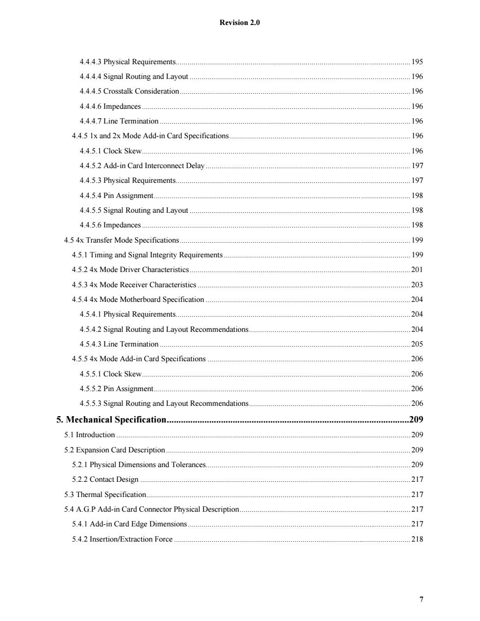
Revision 2.0 4.4.4.3 Physical Requirements.. .195 4.4.4.4 Signal Routing and Layout....... 196 4.4.4.5 Crosstalk Consideration... 196 4.4.4.6 Impedances.… .196 4.4.4.7 Line Termination....... 196 4.4.5 1x and 2x Mode Add-in Card Specifications 196 4.4.5.1 Clock Skew................... 196 4.4.5.2 Add-in Card Interconnect Delay. 197 4.4.5.3 Physical Requirements. 197 4.4.5.4 Pin Assignment............... 198 4.4.5.5 Signal Routing and Layout 198 4.4.5.6 Impedances. 198 4.5 4x Transfer Mode Specifications.... 199 4.5.1 Timing and Signal Integrity Requirements 199 4.5.2 4x Mode Driver Characteristics............... 201 4.5.3 4x Mode Receiver Characteristics............... 203 4.5.4 4x Mode Motherboard Specification. 204 4.5.4.1 Physical Requirements..................... 204 4.5.4.2 Signal Routing and Layout Recommendations 204 4.5.4.3 Line Termination.............. 205 4.5.5 4x Mode Add-in Card Specifications................. 206 4.5.5.1 Clock Skew.............. 206 4.5.5.2 Pin Assignment.................... 206 4.5.5.3 Signal Routing and Layout Recommendations. 206 5.Mechanical Specification............. .209 5.I Introduction 209 5.2 Expansion Card Description........ 209 5.2.1 Physical Dimensions and Tolerances... 209 5.2.2 Contact Design. 217 5.3 Thermal Specification. 217 5.4 A.G.P Add-in Card Connector Physical Description. 217 5.4.1 Add-in Card Edge Dimensions.......... 217 5.4.2 Insertion/Extraction Force .218 7
Revision 2.0 7 4.4.4.3 Physical Requirements....................................................................................................................... 195 4.4.4.4 Signal Routing and Layout ................................................................................................................ 196 4.4.4.5 Crosstalk Consideration..................................................................................................................... 196 4.4.4.6 Impedances ........................................................................................................................................ 196 4.4.4.7 Line Termination ............................................................................................................................... 196 4.4.5 1x and 2x Mode Add-in Card Specifications............................................................................................ 196 4.4.5.1 Clock Skew........................................................................................................................................ 196 4.4.5.2 Add-in Card Interconnect Delay........................................................................................................ 197 4.4.5.3 Physical Requirements....................................................................................................................... 197 4.4.5.4 Pin Assignment.................................................................................................................................. 198 4.4.5.5 Signal Routing and Layout ................................................................................................................ 198 4.4.5.6 Impedances ........................................................................................................................................ 198 4.5 4x Transfer Mode Specifications..................................................................................................................... 199 4.5.1 Timing and Signal Integrity Requirements............................................................................................... 199 4.5.2 4x Mode Driver Characteristics................................................................................................................ 201 4.5.3 4x Mode Receiver Characteristics ............................................................................................................ 203 4.5.4 4x Mode Motherboard Specification ........................................................................................................ 204 4.5.4.1 Physical Requirements....................................................................................................................... 204 4.5.4.2 Signal Routing and Layout Recommendations.................................................................................. 204 4.5.4.3 Line Termination ............................................................................................................................... 205 4.5.5 4x Mode Add-in Card Specifications ....................................................................................................... 206 4.5.5.1 Clock Skew........................................................................................................................................ 206 4.5.5.2 Pin Assignment.................................................................................................................................. 206 4.5.5.3 Signal Routing and Layout Recommendations.................................................................................. 206 5. Mechanical Specification.......................................................................................................209 5.1 Introduction ..................................................................................................................................................... 209 5.2 Expansion Card Description ............................................................................................................................ 209 5.2.1 Physical Dimensions and Tolerances........................................................................................................ 209 5.2.2 Contact Design ......................................................................................................................................... 217 5.3 Thermal Specification...................................................................................................................................... 217 5.4 A.G.P Add-in Card Connector Physical Description....................................................................................... 217 5.4.1 Add-in Card Edge Dimensions................................................................................................................. 217 5.4.2 Insertion/Extraction Force ........................................................................................................................ 218

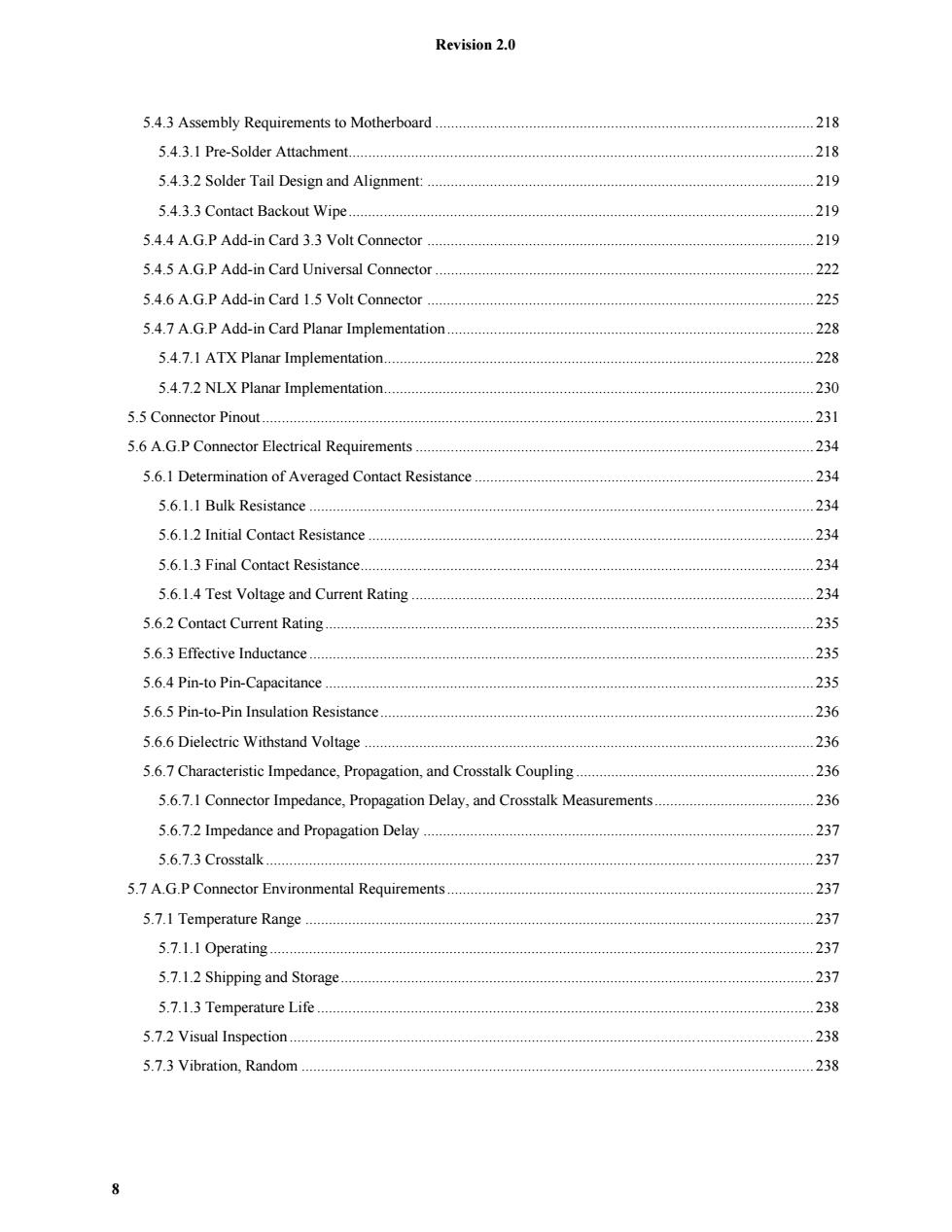
Revision 2.0 5.4.3 Assembly Requirements to Motherboard. 218 5.4.3.1 Pre-Solder Attachment.................... 218 5.4.3.2 Solder Tail Design and Alignment: 219 5.4.3.3 Contact Backout Wipe....... .P 219 5.4.4 A.G.P Add-in Card 3.3 Volt Connector... 219 5.4.5 A.G.P Add-in Card Universal Connector 222 5.4.6 A.G.P Add-in Card 1.5 Volt Connector.... 225 5.4.7 A.G.P Add-in Card Planar Implementation.. 228 5.4.7.1 ATX Planar Implementation.... 228 5.4.7.2 NLX Planar Implementation........... 230 5.5 Connector Pinout... 231 5.6 A.G.P Connector Electrical Requirements....... 234 5.6.1 Determination of Averaged Contact Resistance 234 5.6.1.1 Bulk Resistance. 234 5.6.1.2 Initial Contact Resistance. 234 5.6.1.3 Final Contact Resistance........... 234 5.6.1.4 Test Voltage and Current Rating 234 5.6.2 Contact Current Rating. 235 5.6.3 Effective Inductance....... 235 5.6.4 Pin-to Pin-Capacitance 235 5.6.5 Pin-to-Pin Insulation Resistance............... 236 5.6.6 Dielectric Withstand Voltage..... 236 5.6.7 Characteristic Impedance,Propagation,and Crosstalk Coupling.... 236 5.6.7.1 Connector Impedance,Propagation Delay,and Crosstalk Measurements...... 236 5.6.7.2 Impedance and Propagation Delay...... 237 5.6.7.3 Crosstalk. 237 5.7 A.G.P Connector Environmental Requirements. 237 5.7.1 Temperature Range.................... 237 5.7.1.1 Operating...... 237 5.7.1.2 Shipping and Storage. 237 5.7.1.3 Temperature Life. 238 5.7.2 Visual Inspection....... 238 5.7.3 Vibration,Random................. 238 8
Revision 2.0 8 5.4.3 Assembly Requirements to Motherboard ................................................................................................. 218 5.4.3.1 Pre-Solder Attachment....................................................................................................................... 218 5.4.3.2 Solder Tail Design and Alignment: ................................................................................................... 219 5.4.3.3 Contact Backout Wipe....................................................................................................................... 219 5.4.4 A.G.P Add-in Card 3.3 Volt Connector ................................................................................................... 219 5.4.5 A.G.P Add-in Card Universal Connector ................................................................................................. 222 5.4.6 A.G.P Add-in Card 1.5 Volt Connector ................................................................................................... 225 5.4.7 A.G.P Add-in Card Planar Implementation .............................................................................................. 228 5.4.7.1 ATX Planar Implementation.............................................................................................................. 228 5.4.7.2 NLX Planar Implementation.............................................................................................................. 230 5.5 Connector Pinout ............................................................................................................................................. 231 5.6 A.G.P Connector Electrical Requirements ...................................................................................................... 234 5.6.1 Determination of Averaged Contact Resistance ....................................................................................... 234 5.6.1.1 Bulk Resistance ................................................................................................................................. 234 5.6.1.2 Initial Contact Resistance .................................................................................................................. 234 5.6.1.3 Final Contact Resistance.................................................................................................................... 234 5.6.1.4 Test Voltage and Current Rating ....................................................................................................... 234 5.6.2 Contact Current Rating............................................................................................................................. 235 5.6.3 Effective Inductance ................................................................................................................................. 235 5.6.4 Pin-to Pin-Capacitance ............................................................................................................................. 235 5.6.5 Pin-to-Pin Insulation Resistance............................................................................................................... 236 5.6.6 Dielectric Withstand Voltage ................................................................................................................... 236 5.6.7 Characteristic Impedance, Propagation, and Crosstalk Coupling ............................................................. 236 5.6.7.1 Connector Impedance, Propagation Delay, and Crosstalk Measurements ......................................... 236 5.6.7.2 Impedance and Propagation Delay .................................................................................................... 237 5.6.7.3 Crosstalk............................................................................................................................................ 237 5.7 A.G.P Connector Environmental Requirements .............................................................................................. 237 5.7.1 Temperature Range .................................................................................................................................. 237 5.7.1.1 Operating ........................................................................................................................................... 237 5.7.1.2 Shipping and Storage......................................................................................................................... 237 5.7.1.3 Temperature Life ............................................................................................................................... 238 5.7.2 Visual Inspection ...................................................................................................................................... 238 5.7.3 Vibration, Random ................................................................................................................................... 238

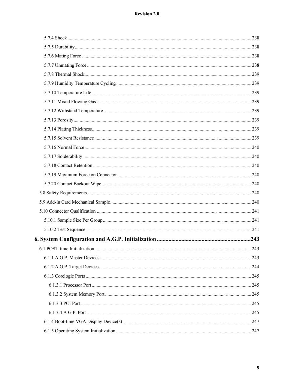
Revision 2.0 5.7.4 Shock 238 5.7.5 Durability..... 238 5.7.6 Mating Force 238 5.7.7 Unmating Force.......... 238 5.7.8 Thermal Shock. 239 5.7.9 Humidity Temperature Cycling 239 5.7.10 Temperature Life...... 239 5.7.11 Mixed Flowing Gas:... 239 5.7.12 Withstand Temperature 239 5.7.13 Porosity. 239 5.7.14 Plating Thickness. 239 5.7.15 Solvent Resistance..... 239 5.7.16 Normal Force.... 240 5.7.17 Solderability.. 240 5.7.18 Contact Retention. 240 5.7.19 Maximum Force on Connector. ””*.-r-r- 240 5.7.20 Contact Backout Wipe.... 240 5.8 Safety Requirements..... 240 5.9 Add-in Card Mechanical Sample. 240 5.10 Connector Qualification.... 241 5.10.1 Sample Size Per Group............ 241 5.10.2 Test Sequence. 241 6.System Configuration and A.G.P.Initialization.. 243 6.1 POST-time Initialization.. 243 6.1.1 A.G.P.Master Devices..... 243 6.1.2 A.G.P.Target Devices.... .244 6.1.3 Corelogic Ports....... 245 6.1.3.1 Processor Port......... 245 6.1.3.2 System Memory Port. 245 6.1.3.3 PCI Port.… 245 6.1.3.4 A.G.P.Port...... 245 6.1.4 Boot-time VGA Display Device(s). 247 6.1.5 Operating System Initialization 247 9
Revision 2.0 9 5.7.4 Shock........................................................................................................................................................ 238 5.7.5 Durability.................................................................................................................................................. 238 5.7.6 Mating Force ............................................................................................................................................ 238 5.7.7 Unmating Force ........................................................................................................................................ 238 5.7.8 Thermal Shock.......................................................................................................................................... 239 5.7.9 Humidity Temperature Cycling ................................................................................................................ 239 5.7.10 Temperature Life .................................................................................................................................... 239 5.7.11 Mixed Flowing Gas: ............................................................................................................................... 239 5.7.12 Withstand Temperature .......................................................................................................................... 239 5.7.13 Porosity................................................................................................................................................... 239 5.7.14 Plating Thickness.................................................................................................................................... 239 5.7.15 Solvent Resistance.................................................................................................................................. 239 5.7.16 Normal Force.......................................................................................................................................... 240 5.7.17 Solderability ........................................................................................................................................... 240 5.7.18 Contact Retention ................................................................................................................................... 240 5.7.19 Maximum Force on Connector ............................................................................................................... 240 5.7.20 Contact Backout Wipe............................................................................................................................ 240 5.8 Safety Requirements........................................................................................................................................ 240 5.9 Add-in Card Mechanical Sample..................................................................................................................... 240 5.10 Connector Qualification ................................................................................................................................ 241 5.10.1 Sample Size Per Group........................................................................................................................... 241 5.10.2 Test Sequence......................................................................................................................................... 241 6. System Configuration and A.G.P. Initialization .................................................................243 6.1 POST-time Initialization.................................................................................................................................. 243 6.1.1 A.G.P. Master Devices ............................................................................................................................. 243 6.1.2 A.G.P. Target Devices.............................................................................................................................. 244 6.1.3 Corelogic Ports ......................................................................................................................................... 245 6.1.3.1 Processor Port.................................................................................................................................... 245 6.1.3.2 System Memory Port ......................................................................................................................... 245 6.1.3.3 PCI Port ............................................................................................................................................. 245 6.1.3.4 A.G.P. Port ........................................................................................................................................ 245 6.1.4 Boot-time VGA Display Device(s)........................................................................................................... 247 6.1.5 Operating System Initialization ................................................................................................................ 247

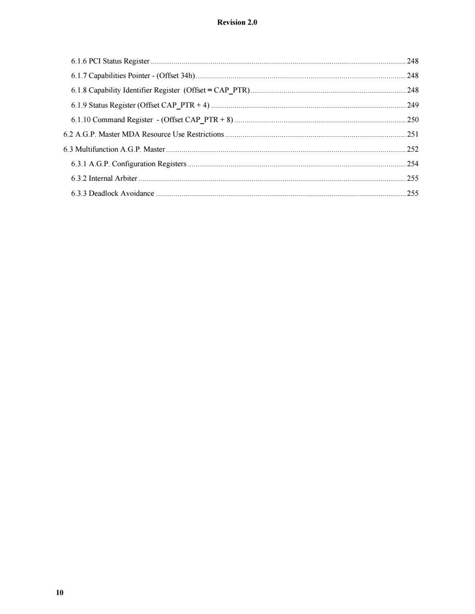
Revision 2.0 6.1.6 PCI Status Register .248 6.1.7 Capabilities Pointer-(Offset 34h)........... .248 6.1.8 Capability Identifier Register (Offset=CAP_PTR) 248 6.1.9 Status Register (Offset CAP PTR+4).................. 249 6.1.10 Command Register -(Offset CAP_PTR+8) 250 6.2 A.G.P.Master MDA Resource Use Restrictions. 251 6.3 Multifunction A.G.P.Master......... 252 6.3.1 A.G.P.Configuration Registers... 254 6.3.2 Internal Arbiter............ 255 6.3.3 Deadlock Avoidance................ 255 10
Revision 2.0 10 6.1.6 PCI Status Register................................................................................................................................... 248 6.1.7 Capabilities Pointer - (Offset 34h)............................................................................................................ 248 6.1.8 Capability Identifier Register (Offset = CAP_PTR)................................................................................ 248 6.1.9 Status Register (Offset CAP_PTR + 4) .................................................................................................... 249 6.1.10 Command Register - (Offset CAP_PTR + 8) ........................................................................................ 250 6.2 A.G.P. Master MDA Resource Use Restrictions ............................................................................................. 251 6.3 Multifunction A.G.P. Master ........................................................................................................................... 252 6.3.1 A.G.P. Configuration Registers ................................................................................................................ 254 6.3.2 Internal Arbiter ......................................................................................................................................... 255 6.3.3 Deadlock Avoidance ................................................................................................................................ 255