Engineering Thermodynamics I Lecture 39-40 Chapter 10 Vapor and Combined Power Systems Spring,5/4/2018 Prof.,Dr.Yonghua HUANG http://cc.sjtu.edu.cn/G2S/site/thermo.html 上游充通大学 May4,2018 1 SHANGHAI JLAO TONG UNIVERSITY
May 4, 2018 1 Engineering Thermodynamics I Lecture 39-40 Spring, 5/4/2018 Prof., Dr. Yonghua HUANG Chapter 10 Vapor and Combined Power Systems http://cc.sjtu.edu.cn/G2S/site/thermo.html
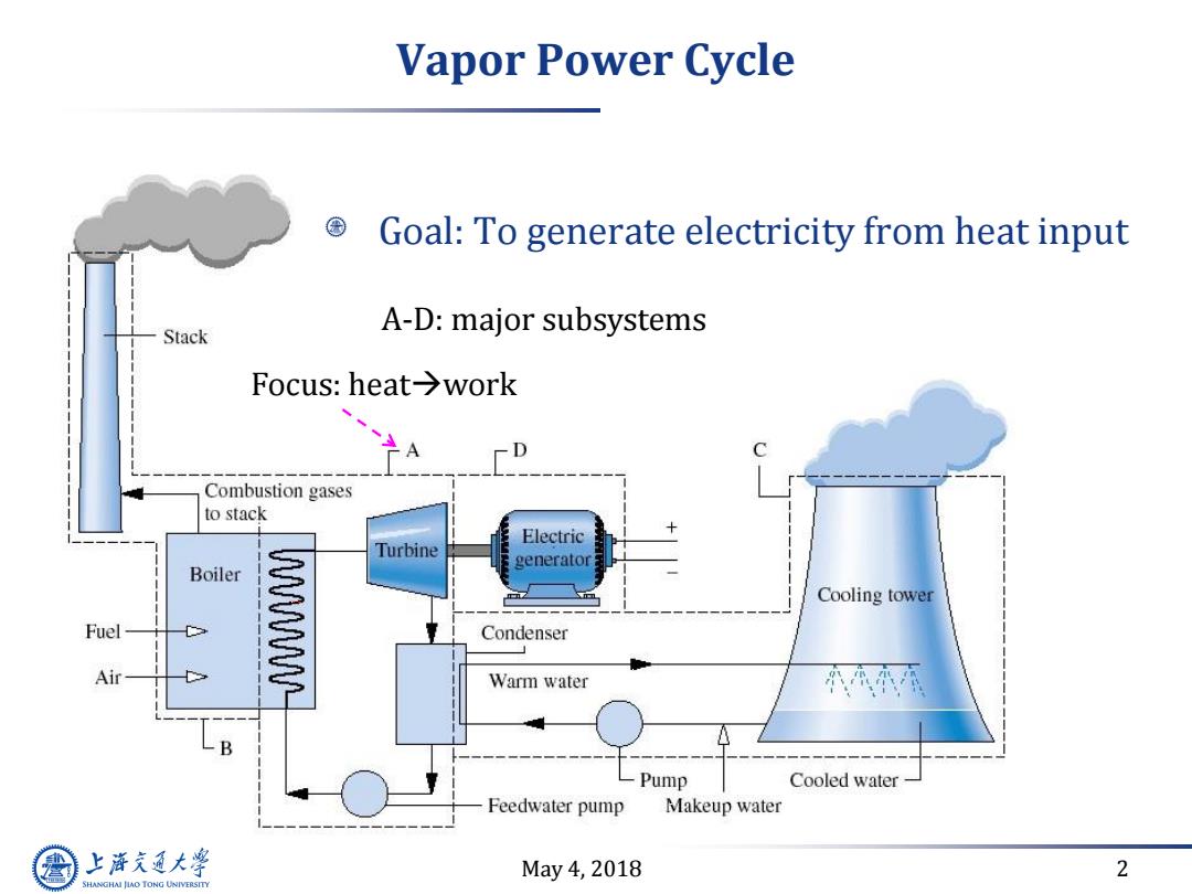
Vapor Power Cycle Goal:To generate electricity from heat input Stack A-D:major subsystems Focus::heat→work D C Combustion gases to stack Electric Turbine generator Boiler Cooling tower Fuel W Condenser Air Warm water B Pump Cooled water Feedwater pump Makeup water 上游充通大学 May4,2018 2 SHANGHAI JIAO TONG UNIVERSITY
May 4, 2018 2 Vapor Power Cycle Goal: To generate electricity from heat input A-D: major subsystems Focus: heatwork
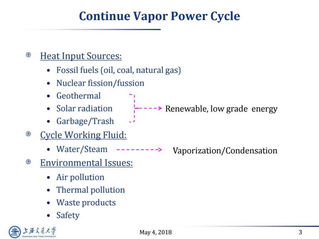
Continue Vapor Power Cycle Heat Input Sources: Fossil fuels (oil,coal,natural gas) Nuclear fission/fussion ●Geothermal 。Solar radiation --->Renewable,low grade energy ·Garbage/Trash Cycle Working Fluid: ·Water/Steam Vaporization/Condensation Environmental Issues: ●Air pollution ·Thermal pollution ·Waste products ·Safety 上游通大学 May4,2018 3 SHANGHAI JLAO TONG UNIVERSITY
May 4, 2018 3 Continue Vapor Power Cycle Heat Input Sources: • Fossil fuels (oil, coal, natural gas) • Nuclear fission/fussion • Geothermal • Solar radiation • Garbage/Trash Cycle Working Fluid: • Water/Steam Environmental Issues: • Air pollution • Thermal pollution • Waste products • Safety Vaporization/Condensation Renewable, low grade energy
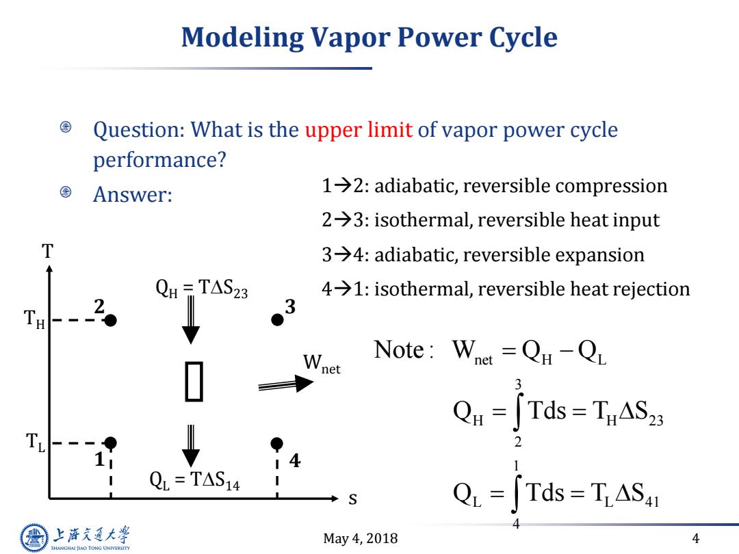
Modeling Vapor Power Cycle Question:What is the upper limit of vapor power cycle performance? 国 Answer: 1→2:adiabatic,reversible compression 2→3:isothermal,reversible heat input T 3→4:adiabatic,reversible expansion QH-TAS23 4>1:isothermal,reversible heat rejection 2。 3 ● Wnet Note:Whet =Qu-QL Qu=[Tds=TnASz T. 14 QL=TAS14 QL =Tds TiASa 上游充通大 May4,2018 4 SHANGHAI JLAO TONG UNIVERSITY
May 4, 2018 4 Modeling Vapor Power Cycle Question: What is the upper limit of vapor power cycle performance? Answer: 12: adiabatic, reversible compression 23: isothermal, reversible heat input 34: adiabatic, reversible expansion 41: isothermal, reversible heat rejection net H L 3 H H 23 2 1 L L 41 4 Note : W Q Q Q Tds T S Q Tds T S 1 2 3 4 s T QH = TS23 QL = TS14 Wnet TH TL
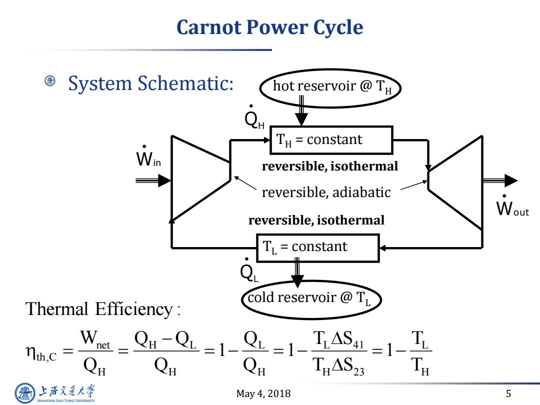
Carnot Power Cycle System Schematic: hot reservoir TH e TH constant reversible,isothermal reversible,adiabatic Wout reversible,isothermal TL=constant Q cold reservoir TL Thermal Efficiency: nth.c =Qn-QL=1-QL=1-TASL=1-T THAS2 上降文通大学 May4,2018 5 SHANGHAI JIAO TONG UNIVERSITY
May 4, 2018 5 Carnot Power Cycle System Schematic: hot reservoir @ TH TH = constant cold reservoir @ TL TL = constant QH QL Win Wout reversible, isothermal reversible, isothermal net H L L L 41 L th,C H H H H 23 H Thermal Efficiency : W Q Q Q T S T 1 1 1 Q Q Q T S T reversible, adiabatic