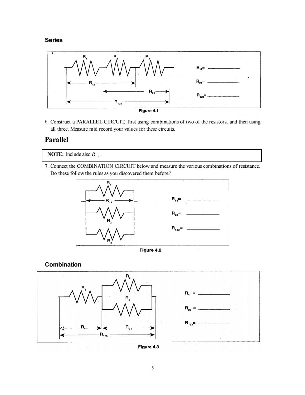
Series R Rz= Figure 4.1 6.Construct a PARALLEL CIRCUIT,first using combinations of two of the resistors,and then using all three.Measure mid record your values for these circuits. Parallel NOTE:Include also R3 7.Connect the COMBINATION CIRCUIT below and measure the various combinations of resistance. Do these follow the rules as you discovered them before? R12= R2= R123 Figure 4.2 Combination R,= R2= R123= -R. Figure 4.3 8
8 Series 6.Construct a PARALLEL CIRCUIT, first using combinations of two of the resistors, and then using all three. Measure mid record your values for these circuits. Parallel NOTE: Include also R13 . 7. Connect the COMBINATION CIRCUIT below and measure the various combinations of resistance. Do these follow the rules as you discovered them before? Combination
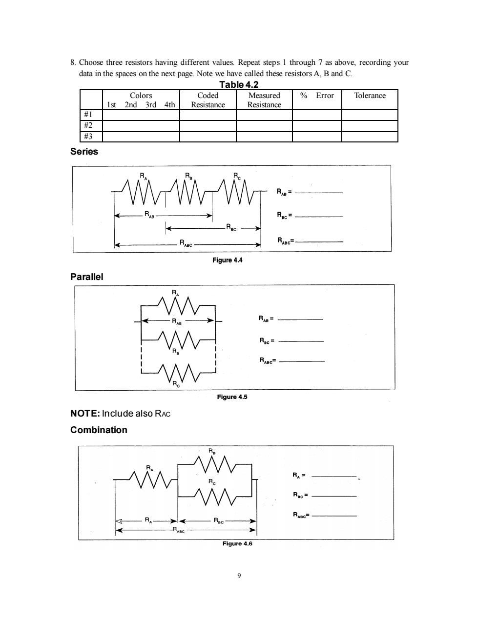
8.Choose three resistors having different values.Repeat steps 1 through 7 as above,recording your data in the spaces on the next page.Note we have called these resistors A,B and C. Table 4.2 Colors Coded Measured Error Tolerance 1st 2nd 3rd 4th Resistance Resistance #1 #视 # Series WWW Figure 4.4 Parallel RAB= Roc= RABc- Figure 4.5 NOTE:Include also RAc Combination RA= RABC= Figure 4.6 9
9 8. Choose three resistors having different values. Repeat steps 1 through 7 as above, recording your data in the spaces on the next page. Note we have called these resistors A, B and C. Table 4.2 Colors 1st 2nd 3rd 4th Coded Resistance Measured Resistance % Error Tolerance #1 #2 #3 Series Parallel NOTE: Include also RAC Combination

Discussion 1.How does the error compare to the coded tolerance for your resistors? 2.What is the apparent rule for combining equal resistances in series circuit?In parallel circuit?Cite evidence from your data to support your conclusions. 3.What is the apparent rule for combining unequal resistances in series circuits?In parallel circuit? Cite evidence from your data to support your conclusions. 4.What is the apparent rule for the total resistance when resistors are added up in series?In parallel? Cite evidence from your data to support your conclusions. Extension Using the same resistance values as you used before plus any wires needed to help build the circuit, design and test the resistance values for another combination of three resistors.As instructed,build circuits with four and five resistors,testing the basic concepts you discovered in this lab. Reference Black 0 Brown 2nd Digit Red 2 Orange 3 1st Digit No.of Zeros Fourth Band Tolerance Yellow 4 None ±20% Green 5 Silver±10% Blue Gold±5% 6 Violet 7 Red ±2% Gray 8 White Figure 4.7 10
10 Discussion 1. How does the % error compare to the coded tolerance for your resistors? 2. What is the apparent rule for combining equal resistances in series circuit? In parallel circuit? Cite evidence from your data to support your conclusions. 3. What is the apparent rule for combining unequal resistances in series circuits? In parallel circuit? Cite evidence from your data to support your conclusions. 4. What is the apparent rule for the total resistance when resistors are added up in series? In parallel? Cite evidence from your data to support your conclusions. Extension Using the same resistance values as you used before plus any wires needed to help build the circuit, design and test the resistance values for another combination of three resistors. As instructed, build circuits with four and five resistors, testing the basic concepts you discovered in this lab. Reference

Experiment 5:Voltages in Circuits EQUIPMENT NEEDED: -AC/DC Electronics Lab Board Wire Leads,Resistors -D-cell Battery Multimeter Purpose The purpose of this lab will be to continue experimenting with the variables that contribute to the operation of an electrical circuit.You should have completed Experiment 4 before working on this lab. Procedure 1.Connect the three equal resistors that you used in Experiment 4 into the series circuit shown below, using the springs to hold the leads of the resistors together without bending them.Connect two wires to the D-cell,carefully noting which wire is connected to the negative and which is connected to the positive. 2.Now use the voltage function on the Multimeter to measure the voltages across the individual resistors and then across the combinations of resistors.Be careful to observe the polarity of the leads(red is+,black is-).Record your readings below. Series Figure 5.1 R1= V1= R2= V2= R3= V3=_ R12= V12= R23= V23= R123= V123= 3.Now connect the parallel circuit below,using all three resistors.Measure the voltage across each of the resistors and the combination,taking care with the polarity as before. 11
11 Experiment 5: Voltages in Circuits EQUIPMENT NEEDED: - AC/DC Electronics Lab Board Wire Leads, Resistors - D-cell Battery - Multimeter Purpose The purpose of this lab will be to continue experimenting with the variables that contribute to the operation of an electrical circuit. You should have completed Experiment 4 before working on this lab. Procedure 1. Connect the three equal resistors that you used in Experiment 4 into the series circuit shown below, using the springs to hold the leads of the resistors together without bending them. Connect two wires to the D-cell, carefully noting which wire is connected to the negative and which is connected to the positive. 2. Now use the voltage function on the Multimeter to measure the voltages across the individual resistors and then across the combinations of resistors. Be careful to observe the polarity of the leads (red is +, black is -). Record your readings below. Series R1=________ V1= R2= V2= R3= V3= R12= V12= R23= V23= R123= V123= 3. Now connect the parallel circuit below, using all three resistors. Measure the voltage across each of the resistors and the combination, taking care with the polarity as before

NOTE:Keep all three resistors connected throughout the time you are making your Measurements.Write down your values as indicated below. Parallel R,= V,= R2= V2= R3= V,= R12 V12a= Figure 5.2 4.Now connect the circuit below and measure the voltages.You can use the resistance readings you took in Experiment 4 for this step. Combination R,= V,= V23= Figure 5.3 5.Use the three unequal resistors that you used in Experiment 4 to construct the circuits shown below.Make the same voltage measurements that you were asked to make before in steps I to 4. Use the same resistors for A,B and C that you used in Experiment 4. +T Vec Figure 5.4 12
12 NOTE: Keep all three resistors connected throughout the time you are making your Measurements. Write down your values as indicated below. Parallel 4. Now connect the circuit below and measure the voltages. You can use the resistance readings you took in Experiment 4 for this step. Combination 5. Use the three unequal resistors that you used in Experiment 4 to construct the circuits shown below. Make the same voltage measurements that you were asked to make before in steps 1 to 4. Use the same resistors for A, B and C that you used in Experiment 4