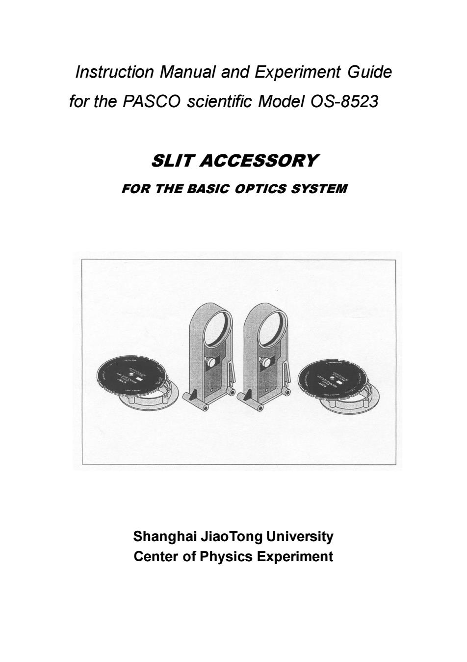
Instruction Manual and Experiment Guide for the PASCO scientific Model OS-8523 SLIT ACCESSORY FOR THE BASIC OPTICS SYSTEM Shanghai JiaoTong University Center of Physics Experiment
Instruction Manual and Experiment Guide for the PASCO scientific Model OS-8523 SLIT ACCESSORY FOR THE BASIC OPTICS SYSTEM Shanghai JiaoTong University Center of Physics Experiment
Table of contents Section Page Intr0 ductic0n..…………………………………… 1 nent......... Assembly.………… 3 Experiments Experiment 1:Diffraction from a Single Slit........................4 Experiment2:Interference from a Double Slit...................... Experiment 3:Comparisons ofDiffractionand Interference Patterns..12
Table of contents Section Page Introduction……………………………………………………………1 Equipment……………………………………………………………..2 Assembly……..……………………………………………………….3 Experiments Experiment 1: Diffraction from a Single Slit...…….……………..4 Experiment 2: Interference from a Double Slit……………..…….7 Experiment 3: Comparisons of Diffraction and Interference Patterns……………………………12
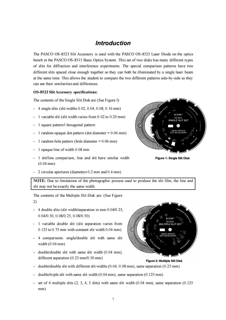
Introduction The PASCO OS-8523 Slit Accessory is used with the PASCO OS-8525 Laser Diode on the optics bench in the PASCO OS-8515 Basic Optics System.This set of two disks has many different types of slits for diffraction and interference experiments.The special comparison patterns have two different slits spaced close enough together so they can both be illuminated by a single laser beam at the same time.This allows the student to compare the two different patterns side-by-side so they can see their similarities and differences. OS-8523 Slit Accessory specifications: The contents of the Single Slit Disk are (See Figure 1) -4 single slits (slit widths 0.02,0.04,0.08,0.16 mm) -1 variable slit (slit width varies from 0.02 to 0.20 mm) SINGLE SLIT SET 1 square patternl hexagonal pattern I random opaque dot pattern (dot diameter=0.06 mm) 1 random hole pattern(hole diameter =0.06 mm) 1 opaque line of width 0.08 mm I slit/line comparison,line and slit have similar width Figure 1:Single Slit Disk (0.04mm) 2 circular apertures(diameters 0.2 mm and 0.4 mm) NOTE:Due to limitations of the photographic process used to produce the slit film,the line and slit may not be exactly the same width. The contents of the Multiple Slit Disk are:(See Figure 2) -4 double slits (slit width/separation in mm:0.04/0.25, 0.04/0.50,0.08/0.25,0.08/0.50) E 0S-8523 1 variable double slit (slit separation varies from MULTIPLE SLIT SET 0.125 to 0.75 mm with constant slit width 0.04 mm) -4 comparisons:single/double slit with same slit width (0.04 mm) double/double slit with same slit width (0.04 mm), different separation(0.25 mm/0.50 mm) Figure 2:Multiple Slit Disk double/double slit with different slit widths(0.04,0.08 mm),same separation(0.25 mm) double/triple slit with same slit width(0.04 mm),same separation (0.125 mm) set of 4 multiple slits(2,3,4,5 slits)with same slit width(0.04 mm),same separation (0.125 mm)
1 Introduction The PASCO OS-8523 Slit Accessory is used with the PASCO OS-8525 Laser Diode on the optics bench in the PASCO OS-8515 Basic Optics System. This set of two disks has many different types of slits for diffraction and interference experiments. The special comparison patterns have two different slits spaced close enough together so they can both be illuminated by a single laser beam at the same time. This allows the student to compare the two different patterns side-by-side so they can see their similarities and differences. OS-8523 Slit Accessory specifications: The contents of the Single Slit Disk are (See Figure l) - 4 single slits (slit widths 0.02, 0.04, 0.08, 0.16 mm) - 1 variable slit (slit width varies from 0.02 to 0.20 mm) - 1 square pattern1 hexagonal pattern - 1 random opaque dot pattern (dot diameter = 0.06 mm) - 1 random hole pattern (hole diameter = 0.06 mm) - 1 opaque line of width 0.08 mm - 1 slit/line comparison, line and slit have similar width (0.04 mm) - 2 circular apertures (diameters 0.2 mm and 0.4 mm) NOTE: Due to limitations of the photographic process used to produce the slit film, the line and slit may not be exactly the same width. The contents of the Multiple Slit Disk are: (See Figure 2) - 4 double slits (slit width/separation in mm:0.04/0.25, 0.04/0.50, 0.08/0.25, 0.08/0.50) - 1 variable double slit (slit separation varies from 0.125 to 0.75 mm with constant slit width 0.04 mm) - 4 comparisons: single/double slit with same slit width (0.04 mm) - double/double slit with same slit width (0.04 mm), different separation (0.25 mm/0.50 mm) - double/double slit with different slit widths (0.04, 0.08 mm), same separation (0.25 mm) - double/triple slit with same slit width (0.04 mm), same separation (0.125 mm) - set of 4 multiple slits (2, 3, 4, 5 slits) with same slit width (0.04 mm), same separation (0.125 mm)
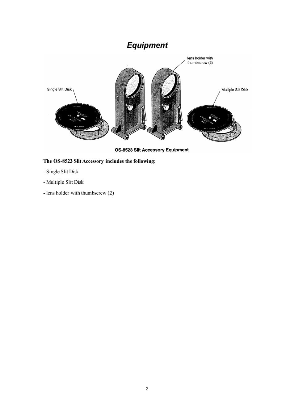
Equipment lens holder with thumbscrew (2) Single Slit Disk Multiple Slit Disk OS-8523 Slit Accessory Equipment The OS-8523 Slit Accessory includes the following: Single Slit Disk Multiple Slit Disk lens holder with thumbscrew(2) 2
2 Equipment The OS-8523 Slit Accessory includes the following: - Single Slit Disk - Multiple Slit Disk - lens holder with thumbscrew (2)
Assembly Mounting the Slit Accessory to the Optics Bench attachmen Each of the slit disks is mounted on a ring which snaps into an empty lens holder.The ring should be rotated in the lens holder so the slits at the center of thumbscrew the ring are vertical in the holder.See Figure 3. Tighten the thumbscrew on the holder so the ring lens holder cannot rotate during use.To select the desired slits, rotate the disk until it clicks into place with the desired slits at the center of the holder. Figure 3:Slit Accessory and Lens Holder NOTE:All slits are vertical EXCEPT the comparison slits which are horizontal.The comparison slits are purposely horizontal because the wide laser diode beam will cover both slits to be compared.If you try to rotate these slits to the vertical position,the laser beam may not be large enough to illuminate both slits at the same time. To align the laser beam and the slits,place the Diode Laser (OS-8525)at one end of the bench. Place the slit holder on the optics bench a few centimeters from the laser with the disk-side of the holder closest to the laser. See Figure 3.Plug in the Diode Laser and turn it on Adjust the position of the laser beam from left-to-right og and up-and-down until the beam is centered on the slit. Once this position is set,it is not necessary to make any further adjustments of the laser beam when viewing Input jack (9VDC) any of the slits on the disk.When you rotate the disk to a new slit,the laser beam will be already aligned.The slits click into place so you can easily change from one optics bench slit to the next,even in the dark. Figure 4:Using the Slit Accessory with the Diode Laser
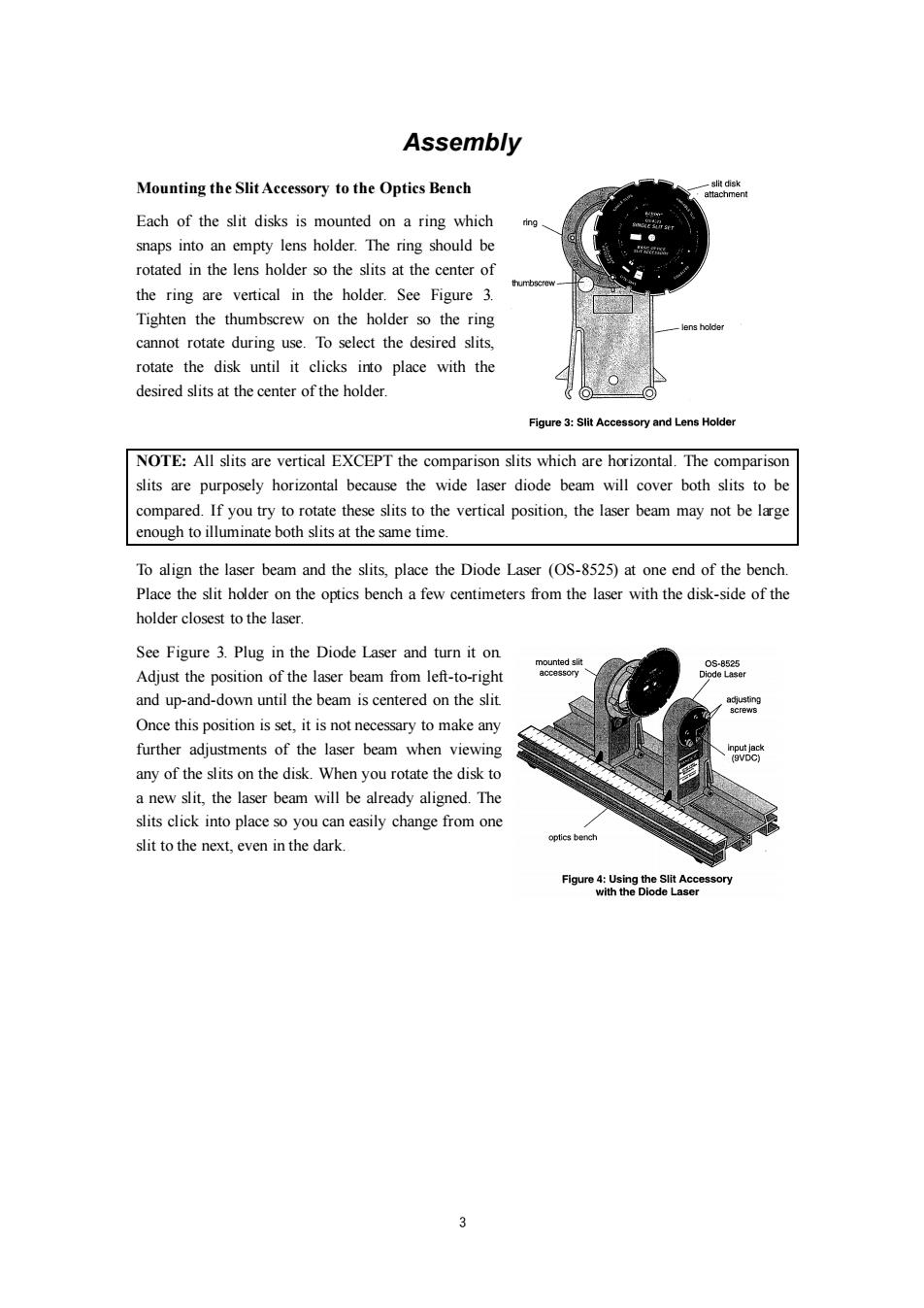
3 Assembly Mounting the Slit Accessory to the Optics Bench Each of the slit disks is mounted on a ring which snaps into an empty lens holder. The ring should be rotated in the lens holder so the slits at the center of the ring are vertical in the holder. See Figure 3. Tighten the thumbscrew on the holder so the ring cannot rotate during use. To select the desired slits, rotate the disk until it clicks into place with the desired slits at the center of the holder. NOTE: All slits are vertical EXCEPT the comparison slits which are horizontal. The comparison slits are purposely horizontal because the wide laser diode beam will cover both slits to be compared. If you try to rotate these slits to the vertical position, the laser beam may not be large enough to illuminate both slits at the same time. To align the laser beam and the slits, place the Diode Laser (OS-8525) at one end of the bench. Place the slit holder on the optics bench a few centimeters from the laser with the disk-side of the holder closest to the laser. See Figure 3. Plug in the Diode Laser and turn it on. Adjust the position of the laser beam from left-to-right and up-and-down until the beam is centered on the slit. Once this position is set, it is not necessary to make any further adjustments of the laser beam when viewing any of the slits on the disk. When you rotate the disk to a new slit, the laser beam will be already aligned. The slits click into place so you can easily change from one slit to the next, even in the dark