Experiment 2:Light in Circuits EQUIPMENT NEEDED: -AC/DC Electronics Lab Board:Wire Leads -(2)D-cell Batteries -Graph Paper Purpose The purpose of this lab is to determine how light bulbs behave in different circuit arrangements. Different ways of connecting two batteries will also be investigated. Procedure PARTA NOTE:Due to variations from bulb to bulb,the brightness of one bulb may be substantially different from the brightness of another bulb in"identical"situations. 1.Use two pieces of wire to connect a single light bulb to one of the D-cells in such a way that the light will glow.Include a "switch"to turn the light on and off,preventing it from being on continuously.(You should have completed this step in Experiment1.If that is the case,review what you did then.If not,continue with this step.) 2.Use additional wires as needed to connect a second light into the circuit in such a way that it is also lighted.Discuss your plans with your lab partner before you begin.Once you have achieved success, sketch the connections that you made in the form of a circuit diagram using standard symbols. Annotate your circuit diagram by making appropriate notes to the side indicating what happened with that particular circuit. NOTE:Is your original light the same brightness,or was it brighter or dimmer than it was during step 1?Can you explain any differences in the brightness,or why it is the same? 3.If one of the light bulbs is unscrewed,does the other bulb go out or does it stay on.Why or why not? 4.Design a circuit that will allow you to light all three lights,with each one being equally bright Draw the circuit diagram once you have been successful.If you could characterize the circuit as being a series or parallel circuit,which would it be?What happens if you unscrew one of the bulbs? Explain. 5.Design another circuit which will also light all three bulbs,but with the bulbs all being equally bright,even though they may be brighter or dimmer than in step 4.Try it.When you are successful, draw the circuit diagram.What happens if you unscrew one of the bulbs?Explain. 6.Devise a circuit which will light two bulbs at the same intensity,but the third at a different intensity. Try it.When successful,draw the circuit diagram.What happens if you unscrew one of the bulbs? Explain. NOTE:Are there any generalizations that you can state about different connections to a set of lights?
3 Experiment 2: Light in Circuits EQUIPMENT NEEDED: - AC/DC Electronics Lab Board: Wire Leads - (2) D-cell Batteries - Graph Paper Purpose The purpose of this lab is to determine how light bulbs behave in different circuit arrangements. Different ways of connecting two batteries will also be investigated. Procedure PART A NOTE: Due to variations from bulb to bulb, the brightness of one bulb may be substantially different from the brightness of another bulb in "identical" situations. 1. Use two pieces of wire to connect a single light bulb to one of the D-cells in such a way that the light will glow. Include a "switch'' to turn the light on and off, preventing it from being on continuously. (You should have completed this step in Experiment1. If that is the case, review what you did then. If not, continue with this step.) 2.Use additional wires as needed to connect a second light into the circuit in such a way that it is also lighted. Discuss your plans with your lab partner before you begin. Once you have achieved success, sketch the connections that you made in the form of a circuit diagram using standard symbols. Annotate your circuit diagram by making appropriate notes to the side indicating what happened with that particular circuit. NOTE: Is your original light the same brightness, or was it brighter or dimmer than it was during step 1? Can you explain any differences in the brightness, or why it is the same? 3. If one of the light bulbs is unscrewed, does the other bulb go out or does it stay on. Why or why not? 4. Design a circuit that will allow you to light all three lights, with each one being equally bright. Draw the circuit diagram once you have been successful. If you could characterize the circuit as being a series or parallel circuit, which would it be? What happens if you unscrew one of the bulbs? Explain. 5. Design another circuit which will also light all three bulbs, but with the bulbs all being equally bright, even though they may be brighter or dimmer than in step 4. Try it. When you are successful, draw the circuit diagram. What happens if you unscrew one of the bulbs? Explain. 6. Devise a circuit which will light two bulbs at the same intensity, but the third at a different intensity. Try it. When successful, draw the circuit diagram. What happens if you unscrew one of the bulbs? Explain. NOTE: Are there any generalizations that you can state about different connections to a set of lights?
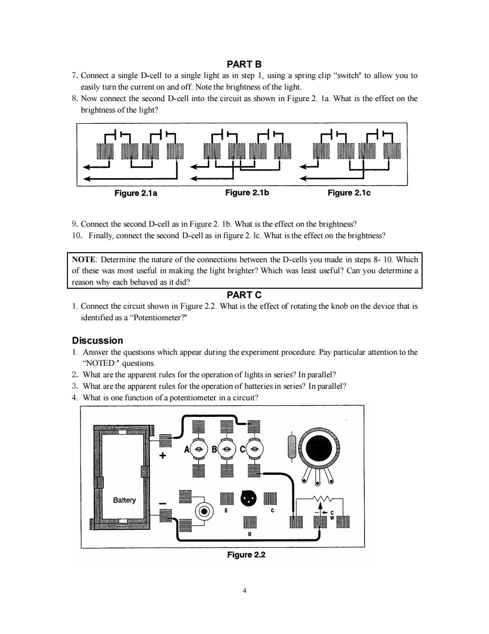
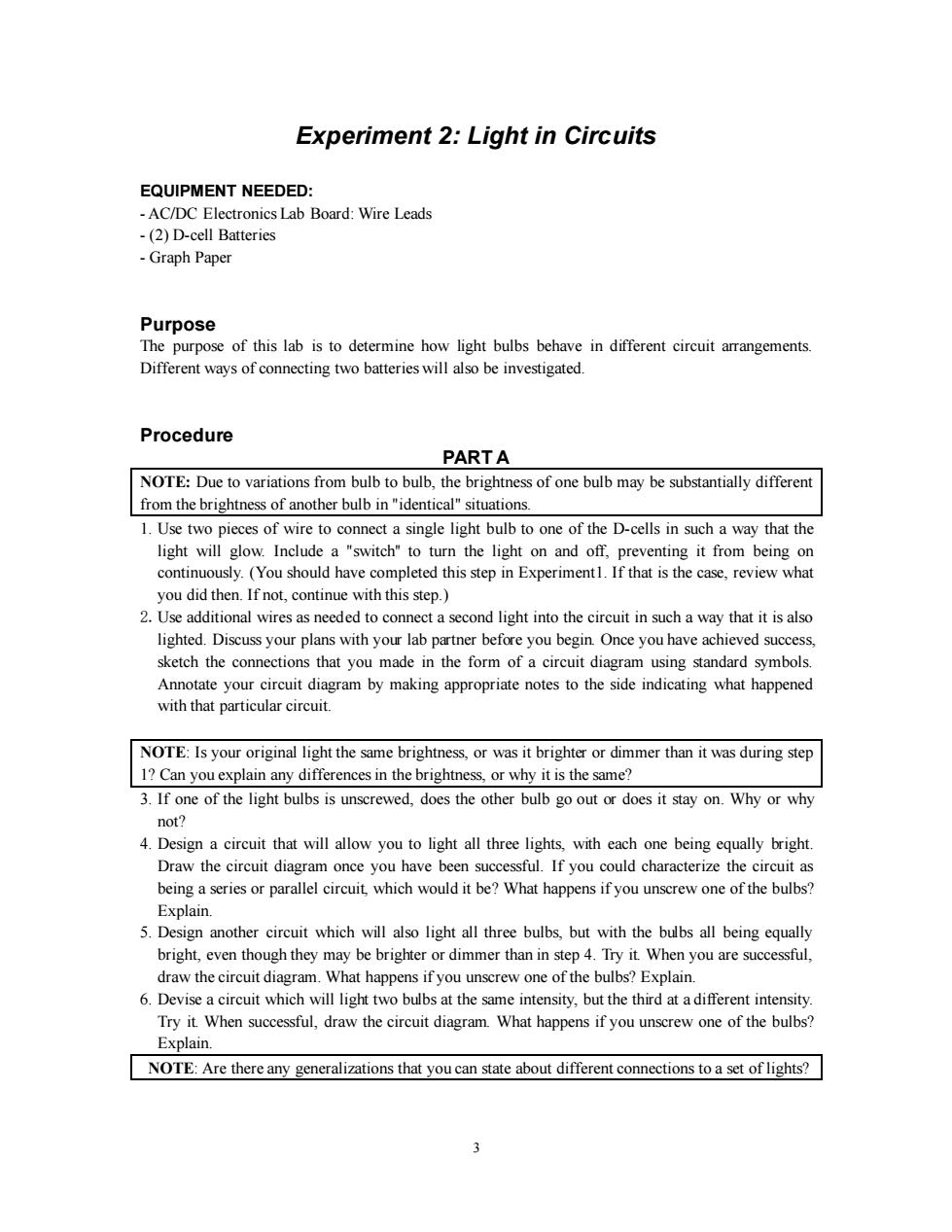
PART B 7.Connect a single D-cell to a single light as in step 1,using a spring clip "switch"to allow you to easily turn the current on and off.Note the brightness of the light. 8.Now connect the second D-cell into the circuit as shown in Figure 2.la.What is the effect on the brightness of the light? h的 Figure 2.1a Figure 2.1b Figure 2.1c 9.Connect the second D-cell as in Figure 2.1b.What is the effect on the brightness? 10.Finally,connect the second D-cell as in figure 2.Ic.What is the effect on the brightness? NOTE:Determine the nature of the connections between the D-cells you made in steps 8-10.Which of these was most useful in making the light brighter?Which was least useful?Can you determine a reason why each behaved as it did? PART C 1.Connect the circuit shown in Figure 2.2.What is the effect of rotating the knob on the device that is identified as a"Potentiometer?" Discussion 1.Answer the questions which appear during the experiment procedure.Pay particular attention to the "NOTED:"questions. 2.What are the apparent rules for the operation of lights in series?In parallel? 3.What are the apparent rules for the operation of batteries in series?In parallel? 4.What is one function of a potentiometer in a circuit? Battery 8 Figure 2.2
4 PART B 7.Connect a single D-cell to a single light as in step 1, using a spring clip “switch'' to allow you to easily turn the current on and off. Note the brightness of the light. 8.Now connect the second D-cell into the circuit as shown in Figure 2. 1a. What is the effect on the brightness of the light? 9.Connect the second D-cell as in Figure 2. 1b. What is the effect on the brightness? 10. Finally, connect the second D-cell as in figure 2. lc. What is the effect on the brightness? NOTE: Determine the nature of the connections between the D-cells you made in steps 8- 10. Which of these was most useful in making the light brighter? Which was least useful? Can you determine a reason why each behaved as it did? PART C 1. Connect the circuit shown in Figure 2.2. What is the effect of rotating the knob on the device that is identified as a “Potentiometer?'' Discussion 1. Answer the questions which appear during the experiment procedure. Pay particular attention to the “NOTED:'' questions. 2. What are the apparent rules for the operation of lights in series? In parallel? 3. What are the apparent rules for the operation of batteries in series? In parallel? 4. What is one function of a potentiometer in a circuit?
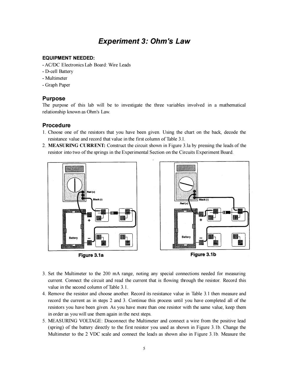
Experiment 3:Ohm's Law EQUIPMENT NEEDED: -AC/DC Electronics Lab Board:Wire Leads -D-cell Battery Multimeter -Graph Paper Purpose The purpose of this lab will be to investigate the three variables involved in a mathematical relationship known as Ohm's Law. Procedure 1.Choose one of the resistors that you have been given.Using the chart on the back,decode the resistance value and record that value in the first column of Table 3.1. 2.MEASURING CURRENT:Construct the circuit shown in Figure 3.la by pressing the leads of the resistor into two of the springs in the Experimental Section on the Circuits Experiment Board. Black(-) B墙ck(H Red (+ Battery Figure 3.1a Figure 3.1b 3.Set the Multimeter to the 200 mA range,noting any special connections needed for measuring current.Connect the circuit and read the current that is flowing through the resistor.Record this value in the second column of Table 3.1. 4.Remove the resistor and choose another.Record its resistance value in Table 3.1 then measure and record the current as in steps 2 and 3.Continue this process until you have completed all of the resistors you have been given.As you have more than one resistor with the same value,keep them in order as you will use them again in the next steps. 5.MEASURING VOLTAGE:Disconnect the Multimeter and connect a wire from the positive lead (spring)of the battery directly to the first resistor you used as shown in Figure 3.1b.Change the Multimeter to the 2 VDC scale and connect the leads as shown also in Figure 3.1b.Measure the 5
5 Experiment 3: Ohm's Law EQUIPMENT NEEDED: - AC/DC Electronics Lab Board: Wire Leads - D-cell Battery - Multimeter - Graph Paper Purpose The purpose of this lab will be to investigate the three variables involved in a mathematical relationship known as Ohm's Law. Procedure 1. Choose one of the resistors that you have been given. Using the chart on the back, decode the resistance value and record that value in the first column of Table 3.l. 2. MEASURING CURRENT: Construct the circuit shown in Figure 3.la by pressing the leads of the resistor into two of the springs in the Experimental Section on the Circuits Experiment Board. 3. Set the Multimeter to the 200 mA range, noting any special connections needed for measuring current. Connect the circuit and read the current that is flowing through the resistor. Record this value in the second column of Table 3.1. 4. Remove the resistor and choose another. Record its resistance value in Table 3.1 then measure and record the current as in steps 2 and 3. Continue this process until you have completed all of the resistors you have been given. As you have more than one resistor with the same value, keep them in order as you will use them again in the next steps. 5. MEASURING VOLTAGE: Disconnect the Multimeter and connect a wire from the positive lead (spring) of the battery directly to the first resistor you used as shown in Figure 3.1b. Change the Multimeter to the 2 VDC scale and connect the leads as shown also in Figure 3.1b. Measure the
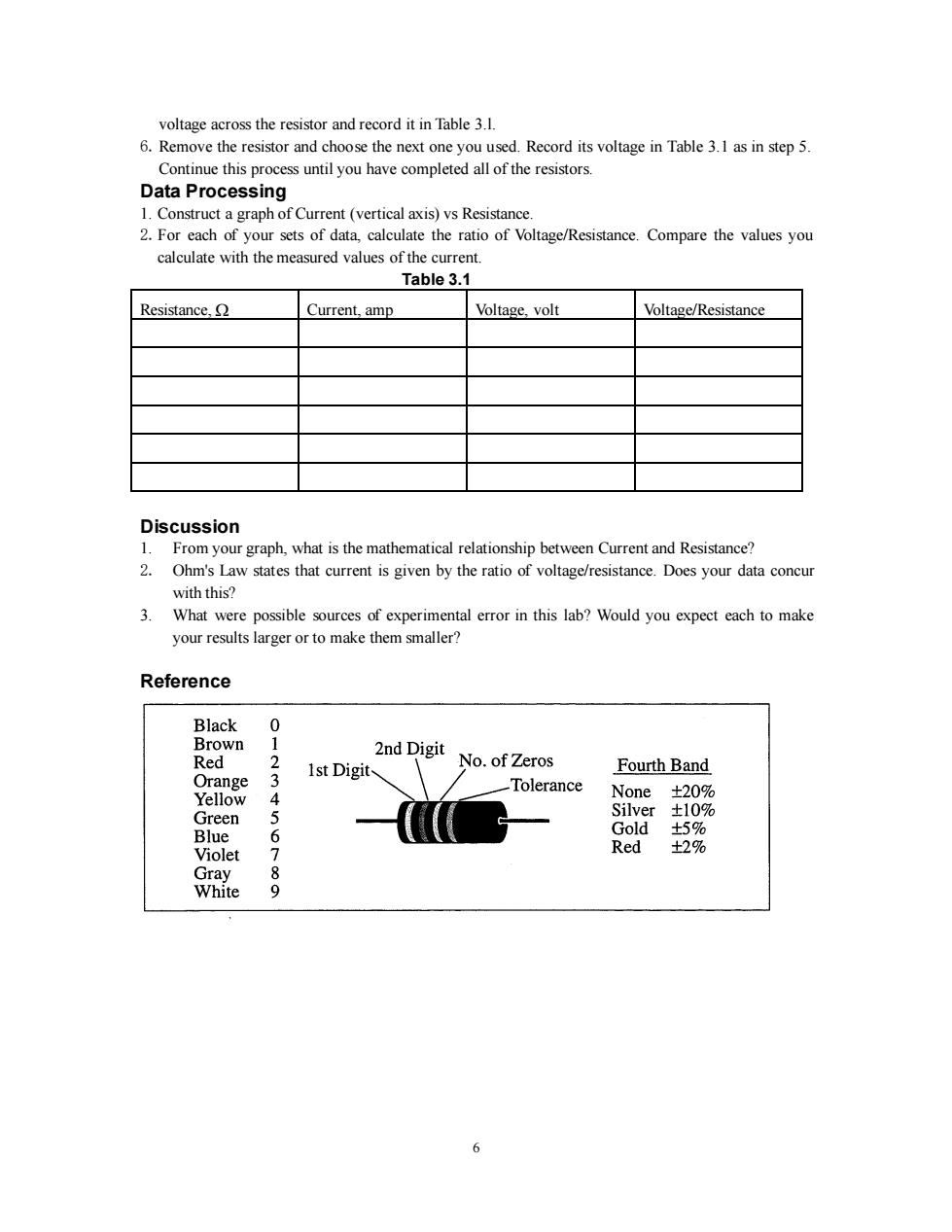
voltage across the resistor and record it in Table 3.1. 6.Remove the resistor and choose the next one you used.Record its voltage in Table 3.1 as in step 5. Continue this process until you have completed all of the resistors. Data Processing 1.Construct a graph of Current(vertical axis)vs Resistance. 2.For each of your sets of data,calculate the ratio of Voltage/Resistance.Compare the values you calculate with the measured values of the current. Table 3.1 Resistance. Current.amp Voltage,volt Voltage/Resistance Discussion 1.From your graph,what is the mathematical relationship between Current and Resistance? 2.Ohm's Law states that current is given by the ratio of voltage/resistance.Does your data concur with this? 3.What were possible sources of experimental error in this lab?Would you expect each to make your results larger or to make them smaller? Reference Black 0 Brown 1 2nd Digit Red 1st Digit No.of Zeros Fourth Band Orange 3 Tolerance Yellow 4 None±20% Green 5 Silver±10% Blue 6 Gold ±5% Violet Red ±2% Gray 8 White 9 6
6 voltage across the resistor and record it in Table 3.l. 6.Remove the resistor and choose the next one you used. Record its voltage in Table 3.1 as in step 5. Continue this process until you have completed all of the resistors. Data Processing 1. Construct a graph of Current (vertical axis) vs Resistance. 2.For each of your sets of data, calculate the ratio of Voltage/Resistance. Compare the values you calculate with the measured values of the current. Table 3.1 Resistance, Current, amp Voltage, volt Voltage/Resistance Discussion 1. From your graph, what is the mathematical relationship between Current and Resistance? 2. Ohm's Law states that current is given by the ratio of voltage/resistance. Does your data concur with this? 3. What were possible sources of experimental error in this lab? Would you expect each to make your results larger or to make them smaller? Reference
Experiment 4:Resistances in Circuits EQUIPMENT NEEDED: -AC/DC Electronics Lab Board:Resistors Multimeter Purpose The purpose of this lab is to begin experimenting with the variables that contribute to the operation of an electrical circuit.This is the first of a three connected labs. Procedure 1.Choose three resistors of the same value.Enter those sets of colors in Table 4.1 below.We will refer to one as #l,another as #2 and the third as #3. 2.Determine the coded value of your resistors.Enter the value in the column labeled "Coded Resistance"in Table 4.1.Enter the Tolerance value as indicated by the color of the fourth band under“Tolerance." 3.Use the Multimeter to measure the resistance of each of your three resistors.Enter these values in Table 4.1. 4.Determine the percentage experimental error of each resistance value and enter it in the appropriate column. Experimental Error=[(|Measured-Coded))/Coded]x 100% Table 4.1 Colors Coded Measured 1st 2nd 3rd 4th Resistance Error Tolerance Resistance #1 #2 #3 5.Now connect the three resistors into the SERIES CIRCUIT,figure 4.1,using the spring clips on the Circuits Experiment Board to hold the leads of the resistors together without bending them. Measure the resistances of the combinations as indicated on the diagram by connecting the leads of the Multimeter between the points at the ends of the arrows
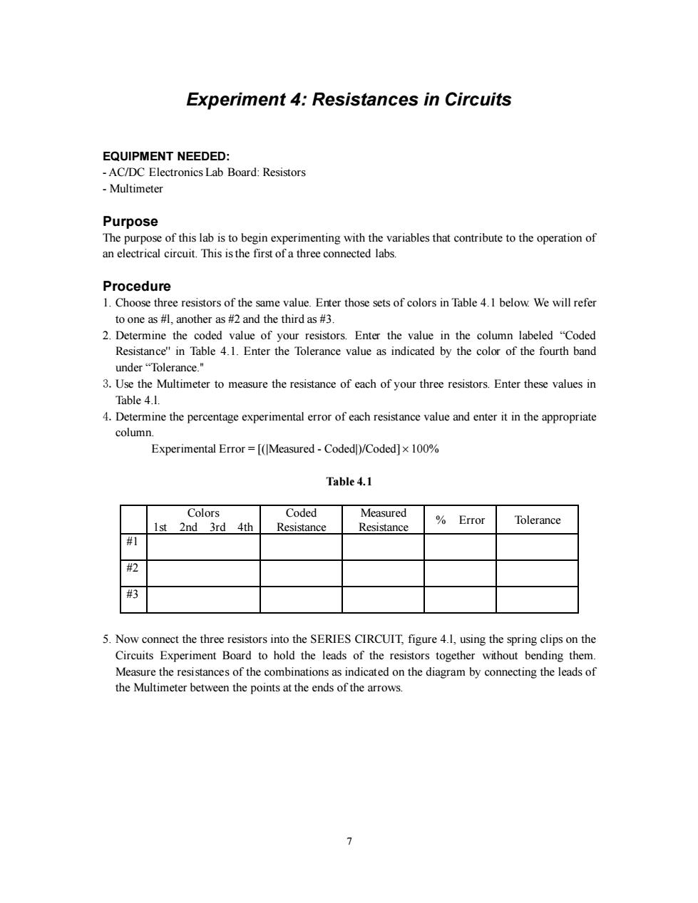
7 Experiment 4: Resistances in Circuits EQUIPMENT NEEDED: - AC/DC Electronics Lab Board: Resistors - Multimeter Purpose The purpose of this lab is to begin experimenting with the variables that contribute to the operation of an electrical circuit. This is the first of a three connected labs. Procedure 1. Choose three resistors of the same value. Enter those sets of colors in Table 4.1 below. We will refer to one as #l, another as #2 and the third as #3. 2. Determine the coded value of your resistors. Enter the value in the column labeled “Coded Resistance'' in Table 4.1. Enter the Tolerance value as indicated by the color of the fourth band under “Tolerance.'' 3.Use the Multimeter to measure the resistance of each of your three resistors. Enter these values in Table 4.l. 4.Determine the percentage experimental error of each resistance value and enter it in the appropriate column. Experimental Error = [(|Measured - Coded|)/Coded] 100% Table 4.1 Colors 1st 2nd 3rd 4th Coded Resistance Measured Resistance % Error Tolerance #1 #2 #3 5. Now connect the three resistors into the SERIES CIRCUIT, figure 4.l, using the spring clips on the Circuits Experiment Board to hold the leads of the resistors together without bending them. Measure the resistances of the combinations as indicated on the diagram by connecting the leads of the Multimeter between the points at the ends of the arrows