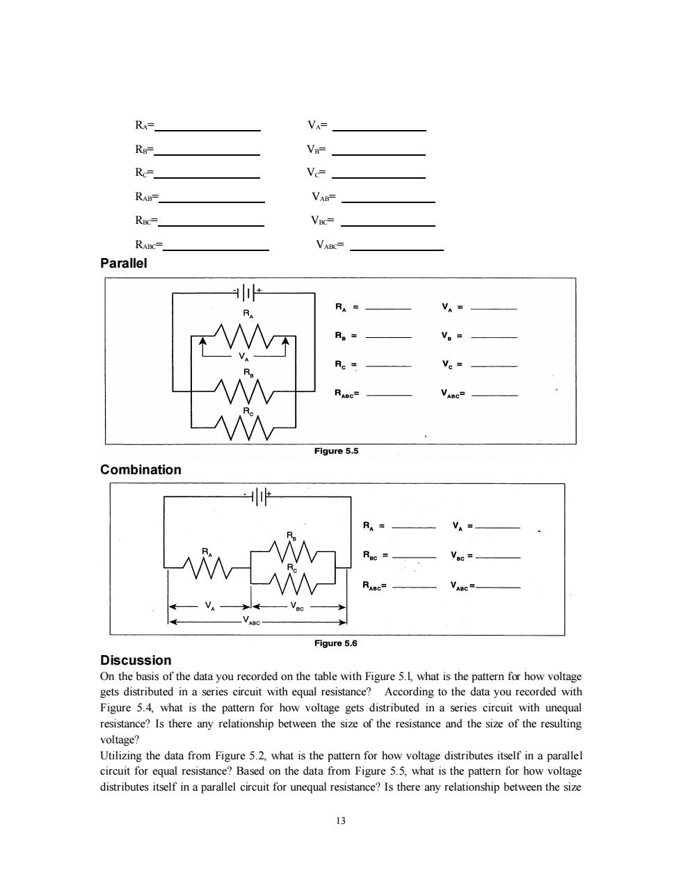
RA=」 VA= Rn= VB= Rc-_ Vc= RABF」 VAB= RBC-_ VBC= RABC=_ VABC= Parallel RA= R VA- R。= V。= R。= V。= RABC= Figure 5.5 Combination RA= V。= Vac= RABc= Figure 5.6 Discussion On the basis of the data you recorded on the table with Figure 5.1,what is the pattern for how voltage gets distributed in a series circuit with equal resistance?According to the data you recorded with Figure 5.4,what is the pattern for how voltage gets distributed in a series circuit with unequal resistance?Is there any relationship between the size of the resistance and the size of the resulting voltage? Utilizing the data from Figure 5.2,what is the pattern for how voltage distributes itself in a parallel circuit for equal resistance?Based on the data from Figure 5.5,what is the pattern for how voltage distributes itself in a parallel circuit for unequal resistance?Is there any relationship between the size 13
13 RA= VA= RB= VB= RC= VC= RAB= VAB= RBC= VBC= RABC= VABC= Parallel Combination Discussion On the basis of the data you recorded on the table with Figure 5.l, what is the pattern for how voltage gets distributed in a series circuit with equal resistance? According to the data you recorded with Figure 5.4, what is the pattern for how voltage gets distributed in a series circuit with unequal resistance? Is there any relationship between the size of the resistance and the size of the resulting voltage? Utilizing the data from Figure 5.2, what is the pattern for how voltage distributes itself in a parallel circuit for equal resistance? Based on the data from Figure 5.5, what is the pattern for how voltage distributes itself in a parallel circuit for unequal resistance? Is there any relationship between the size

of the resistance and the size of the resulting voltage? Do the voltages in your combination circuits (see Figures 5.3 and 5.6)follow the same rules as they did in your circuits which were purely series or parallel?If not,state the rules you see in operation. 以
14 of the resistance and the size of the resulting voltage? Do the voltages in your combination circuits (see Figures 5.3 and 5.6) follow the same rules as they did in your circuits which were purely series or parallel? If not, state the rules you see in operation

Experiment 6:Currents in Circuits EQUIPMENTNEEDED: -AC/DC Electronics Lab Board:Resistors and Wire Leads D-cell Battery -Digital Multimeter Purpose The purpose of this lab will be to continue experimenting with the variables that contribute to the operation of electrical circuits. Procedure 1.Connect the same three resistors that you used in Experiments 3 and 4 into the series circuit shown below,using the springs to hold the leads of the resistors together without bending them.Connect two wires to the D-cell,and carefully note which lead is negative and which is positive. Series 2.Now change the leads in your DMM so that they can be used to measure current.You should be using the scale which goes to a maximum of 200 mA. Be careful to observe the polarity of the leads (red is +black is-).In order to measure current,the circuit must be interrupted,and the current allowed to flow through the meter.Disconnect the Figure 6.1 lead wire from the positive terminal of the battery and connect it to the red (+ lead of the meter.Connect the black(-) lead to Ri,where the wire originally was connected.Record your reading in the table as I.See Figure 6.2. 3.Now move the DMM to the positions indicated in Figure 6.3,each time interrupting the circuit,and carefully Figure 6.2 measuring the current in each one.Complete the table on the top of the back page. NOTE:You will be carrying values from Experiments 3 and 4 into the table on the back. 15
15 Experiment 6: Currents in Circuits EQUIPMENTNEEDED: - AC/DC Electronics Lab Board: Resistors and Wire Leads - D-cell Battery - Digital Multimeter Purpose The purpose of this lab will be to continue experimenting with the variables that contribute to the operation of electrical circuits. Procedure 1.Connect the same three resistors that you used in Experiments 3 and 4 into the series circuit shown below, using the springs to hold the leads of the resistors together without bending them. Connect two wires to the D-cell, and carefully note which lead is negative and which is positive. Series 2. Now change the leads in your DMM so that they can be used to measure current. You should be using the scale which goes to a maximum of 200 mA. Be careful to observe the polarity of the leads (red is +, black is -). In order to measure current, the circuit must be interrupted, and the current allowed to flow through the meter. Disconnect the lead wire from the positive terminal of the battery and connect it to the red (+) lead of the meter. Connect the black (-) lead to R1, where the wire originally was connected. Record your reading in the table as Io. See Figure 6.2. 3. Now move the DMM to the positions indicated in Figure 6.3, each time interrupting the circuit, and carefully measuring the current in each one. Complete the table on the top of the back page. NOTE: You will be carrying values from Experiments 3 and 4 into the table on the back

Figure 6.3 R1= 1。= V R2= I1= V2= R3= I2= V3= R12= I3= V12= R23= V23= R123= V123= 4.Connect the parallel circuit below,using all three resistors.Review the instructions for connecting the DMM as an ammeter in step 2.Connect it first between the positive terminal of the battery and the parallel circuit junction to measure I..Then interrupt the various branches of the parallel circuit and measure the individual branch currents.Record your measurements in the table below. Parallel R1= Io= V= R2= I= V2= R3= I2= V3= 入 R123= I3= V123=」 Figure 6.4 Discussion On the basis of your first set of data,what is the pattern for how current behaves in a series circuit?At this point you should be able to summarize the behavior of all three quantities-resistance,voltage and current-in series circuits. On the basis of your second set of data,are there any patterns to the way that currents behave in a parallel circuit?At this time you should be able to write the general characteristics of currents, voltages and resistances in parallel circuits. 16
16 R1= Io= V1= R2= I1= V2= R3= I2= V3= R12= I3= V12= R23= V23= R123= V123= 4. Connect the parallel circuit below, using all three resistors. Review the instructions for connecting the DMM as an ammeter in step 2. Connect it first between the positive terminal of the battery and the parallel circuit junction to measure Io. Then interrupt the various branches of the parallel circuit and measure the individual branch currents. Record your measurements in the table below. Parallel R1=__________ Io=_________ V1=__________ R2=__________ I1=_________ V2=__________ R3=__________ I2=_________ V3=__________ R123=__________ I3=_________ V123=__________ I4=_________ Discussion On the basis of your first set of data, what is the pattern for how current behaves in a series circuit? At this point you should be able to summarize the behavior of all three quantities - resistance, voltage and current - in series circuits. On the basis of your second set of data, are there any patterns to the way that currents behave in a parallel circuit? At this time you should be able to write the general characteristics of currents, voltages and resistances in parallel circuits

Experiment 7:Kirchhoff's Rules EQUIPMENT NEEDED: -AC/DC Electronics Lab Board:Resistors,Wire Leads -(2)D-cell Batteries -Digital Multimeter(DMM) Purpose The purpose of this lab will be to experimentally demonstrate Kirchhoff s Rules for electrical circuits. Procedure A B R R, Wire Wire Battery Fiqure 7.1a 1.Connect the circuit shown in Figure 7.1 a using any of the resistors you have except the 10Q one. Use Figure 7.1b as a reference along with 7.la as you record your data.Record the resistance values in the table below.With no current flowing (the battery disconnected),measure the total resistance of the circuit between points A and B. 2.With the circuit connected to the battery and the current flowing,measure the voltage across each of the resistors and record the values in the table below.On the circuit diagram in Figure 7.1b, indicate which side of each of the resistors is positive relative to the other end by placing a "+ at that end. 3.Now measure the current through each of the resistors.Interrupt the circuit and place the DMM in series to obtain your reading.Make sure you record each of the individual currents,as well as Figure 7.1b 17
17 Experiment 7: Kirchhoff's Rules EQUIPMENT NEEDED: - AC/DC Electronics Lab Board: Resistors, Wire Leads - (2) D-cell Batteries - Digital Multimeter (DMM) Purpose The purpose of this lab will be to experimentally demonstrate Kirchhoff' s Rules for electrical circuits. Procedure 1. Connect the circuit shown in Figure 7. 1 a using any of the resistors you have except the 10Ω one. Use Figure 7.1b as a reference along with 7.la as you record your data. Record the resistance values in the table below. With no current flowing (the battery disconnected), measure the total resistance of the circuit between points A and B. 2. With the circuit connected to the battery and the current flowing, measure the voltage across each of the resistors and record the values in the table below. On the circuit diagram in Figure 7.1b, indicate which side of each of the resistors is positive relative to the other end by placing a “+'' at that end. 3. Now measure the current through each of the resistors. Interrupt the circuit and place the DMM in series to obtain your reading. Make sure you record each of the individual currents, as well as