三 Alternatively,equations(7.46)are derived below by the inversion of sub- inverse of the stiffness matrix constants are tiplying both sides of the equation by the compliance matrix,which is the fully inverted form of this equation can be obtained directly by premul- where the Ai B and Di make up the laminate stiffness matrix,[E].The (7.42)can be expressed as The general laminate force-deformation equations shown in equations 7.5.1 Inversion of Laminate Force-Deformation Equations in the comparison of predicted and measured laminate compliances. are also used in the derivation of the laminate engineering constants and stresses and strains due to known laminate loads.The inverted equations the inverted equations are derived and used to calculate the lamina compliance matrix instead of the laminate stiffness matrix.In this section, use of the inverted equations means that we must deal with the laminate mation relationships shown in equation(7.41)and equation (7.42).The it is often necessary to use the inverted form of the laminate force-defor- Since the applied loads are generally known rather than the deformations, Derivation and Use of Laminate Compliances with the laminate thickness,f,in equations (7.44) Note that the A can also be found by using the invariants U and U,along -7820:子52.12-645E E E Substituting these results in equations(6.43),we find that the engineering Principles of Composite Material Mechanics Now substituting equations(7.52)in equations(7.49),we have curvatures,we find that where Inverting the last set of partitioned equations (7.51)to solve for the Analysis of Laminates [D]=[D]-[BILATIBI [C]=[B][A] 支-Aia [A*]=[AT inverted form of equations (7.45)as follows: Equations(7.49)and equations(7.50)can be combined to give a partially (M)=[B][AT(N)-[BILAT[BI(K)+[DIK) Substitution of these strains in equations(7.48)gives (e)=[A](N)-[A][BI(K The midplane strains may be obtained from equations(7.47)as (M)=[Bl(e)+[D](K) whereas the moments per unit length are (N)=[A]e)+[B](K) From equations(7.45),the in-plane forces per unit length are G.52 G.51 G.50 超 G.5
where 3 strenoth analvsis will he nresented in section 7.8. hygrothermal stresses will be discussed later in section 7.6,and laminate strength criterion to check each lamina against failure.The analysis of from equations (7.56)can then be used in conjunction with a lamina laminate forces and moments by equations (7.54).The lamina stresses where the midplane strains (e)and curvatures (K)are given in terms of abbreviated matrix notation as the kth lamina are given by equations (7.31),which can be written in a laminate at constant temperature and moisture content,the stresses in known laminate forces and moments is a straightforward procedure.For in equations (7.54),the calculation of lamina stresses and strains from Now that we have the inverted laminate force-deformation relationships 7.5.2 Determination of Lamina Stresses and Strains also be symmetric. and the compliance matrix is matrix form to give 91O6+N2 Since the stiffness matrix [E]is symmetric,the compliance matrix must 益 [A]=[A]-[BIDPIC] Equations(7.52)and equation(7.53)can now be combined in partitioned Principles of Composite Material Mechanics G.59 G.55 圣 here, single uniaxial force per unit length Nx=50 MPa-mm.Determine the resulting Stresses associated with the x and v nvee in on EXAMPLE 7.7 The antisymmetric angle-ply laminate described in example 7.4 is subjected to a Note that since the curvatures vanish for this problem,the stresses do not depend on the distance z. 9 9 stresses in the+45 plies are 鸭 EXAMPLE 7.6 32.44-324 3142 63 Analysis of Laminates 45.22 3142 32.492.4 002920.06226 101042760.0295 36 皮本 -32.44/10002188 where 10 MPa =GPa:Similarly,the stresses in the-45 plies are 56 31.42452282.44 4G2231.4232.44/0002188 0 0-0.0014850.102- 0.02800l Using the inverse of the [A]matrix from example 7.3,we find that (s)=[A'TIN)=[A](N) stresses associated with the x and y axes in each lamina. 3 212 -0.00148518102--01wPg the lamina stiffnesses from example 7.3 in equations(7.56),we find that the where(GPa-mm)1=10-3(MPa-mm)-1.Substituting the above strains and -0.001485 0·.002138 Solution.Due to symmetry,[B]=0 and [A']=[A*]=[A]-1.Since (M)=0 single uniaxial force per unit length Nx=50 MPa-mm.Determine the resulting The symmetric angle-ply laminate described in example 7.3 is subjected to a 三
空 ply,z=0 and the strains are 召 6--0.00143mm/mim :-0002193mmin At the top surface of the #3 ply(-45),or at the bottom surface of the #2 of the #2 ply (+45),z=0.25 mm and the strains are Similarly,at the bottom surface of the #1 ply(-45),or at the top surface #1 ply (-45),z=-0.5 mm and the resulting total strains are the distance z(unlike example 7.6).For example,at the top surface of the tency.Due to the curvatures,the total strains and stresses now depend on where again the factor of 10-3 has been introduced for dimensional consis- -0.02083 10.02861 0.04386 w-0+(-025/(-0.001042)-0.000261mm/mm 86-:-10001434(0250(00--10.001430mm/mm :-0.002193+(-0.25(0-0.002193mm/mm yw-7e13k0-.0+十(0.5t-00010a2)-0000521mm7mm 8-6品+2kg--4.00149+(05(00--000143mm/mm 6:-6)+2K:-0.002198+(-05(00-0.002198mm/mm 1-0.001042mm 0mm-1 -0.02083 0.0程386 -0.02861 0mm/mm -0.001430mm/mm 0.o02193mm/nm -0.02083-0.34831 -0.020830.52625 0.03294 -0.02083 0 0.52625 9.30331 -0.02083 inverting,we find the resulting midplane strains and curvatures to be stiffness matrix from the [A],[B],and [D]matrices in example 7.4 and stiffness matrix as in equation(7.46)or equation (7.54).Forming the full Solution.Since this laminate is not symmetric,we must invert the full 2.39356 0.02083 -0.02083 Principles of Composite Material Mechanics inate is quite complex,even for simple uniaxial loading.This is typical for laminates which exhibit coulino Thus,the stress distribution across the thickness of the antisymmetric lam- #4 Bottom #3 Bottom 恭oe #2 Bottom Location where again 103 Mpa =GPa.Similar calculations for the other plies yield the values shown in the following table: y 9 9 -6.2 皇器 4522 ply (-45),z=0.25 mm and Analysis of Laminates E 民罔 云 37.3 o,(MPa) -12.7 MPa ,(MPa) -32.44356 522 -122 81.42-82.44/0002193 The stresses at the top surface of the #1 ply(-45)are then Yxy=-0.000521mm/mm :-0.00143mm/tmn ex =0.002193mm/mm Finally,at the bottom of the #4 ply (+45),z=+40.5 mm and Yxy=-0.000261mm/mm Ey=-0.00143mm/mm Ex =0.002193mm/mm 1/(/0.0006521 15.5 老号 民 罢 155 1-0.001430)%10e At the top surface of the #4 ply (+45),or at the bottom surface of the #3
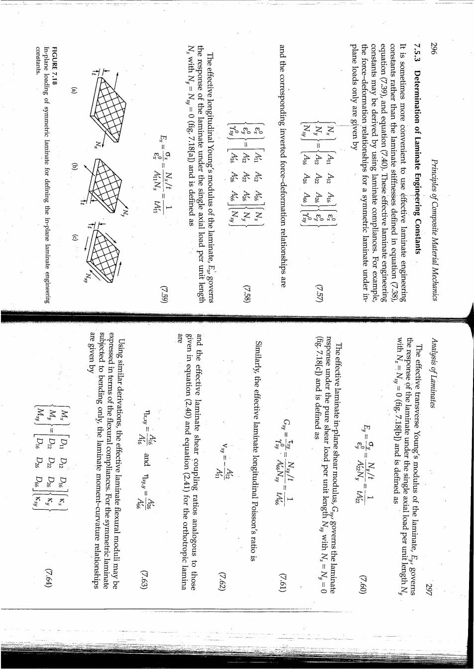
constants. 紫 FIGURE 7.18 In-plane loading of symmetric laminate for defining the in-plane laminate engineeri 品2E N,with Ny=Ny =0 (fig.7.18[a])and is defined as the response of the laminate under the single axial load per unit length The effective longitudinal Young's modulus of the laminate,E governs 厨 示 and the corresponding inverted force-deformation relationships are 子 plane loads only are given by 京 3 茶 余 云 子 the force-deformation relationships for a symmetric laminate under in- constants may be derived by using laminate compliances.For example, equation(7.39),and equation (7.40).These effective laminate engineering constants rather than the laminate stiffnesses defined in equation(7.38), It is sometimes more convenient to use effective laminate engineering 7.5.3 Determination of Laminate Engineering Constants Principles of Composite Material Mechanics 是 G.58 国 are given by 名 expressed in terms of the flexural compliances.For the symmetric laminate subjected to bending only,the laminate moment-curvature relationships Using similar derivations,the effective laminate flexural moduli may be given in equation(2.40)and equation(2.41)for the orthotropic lamina and the effective laminate shear coupling ratios analogous to those Similarly,the effective laminate longitudinal Poisson's ratio is response under the pure shear load per unit length Nay with N.,=Ny=0 (fig.7.18[c])and is defined as Analysis of Laminates g g 之 Nu/t with N,=N=0(fig.7.18[b])and is defined as 茶 The effective laminate in-plane shear modulus,Gygoverns the laminate the response of the laminate under the single axial load per unit length N The effective transverse Young's modulus of the laminate,Ey governs 公。6c (7.63) G.62 公6) 公。60
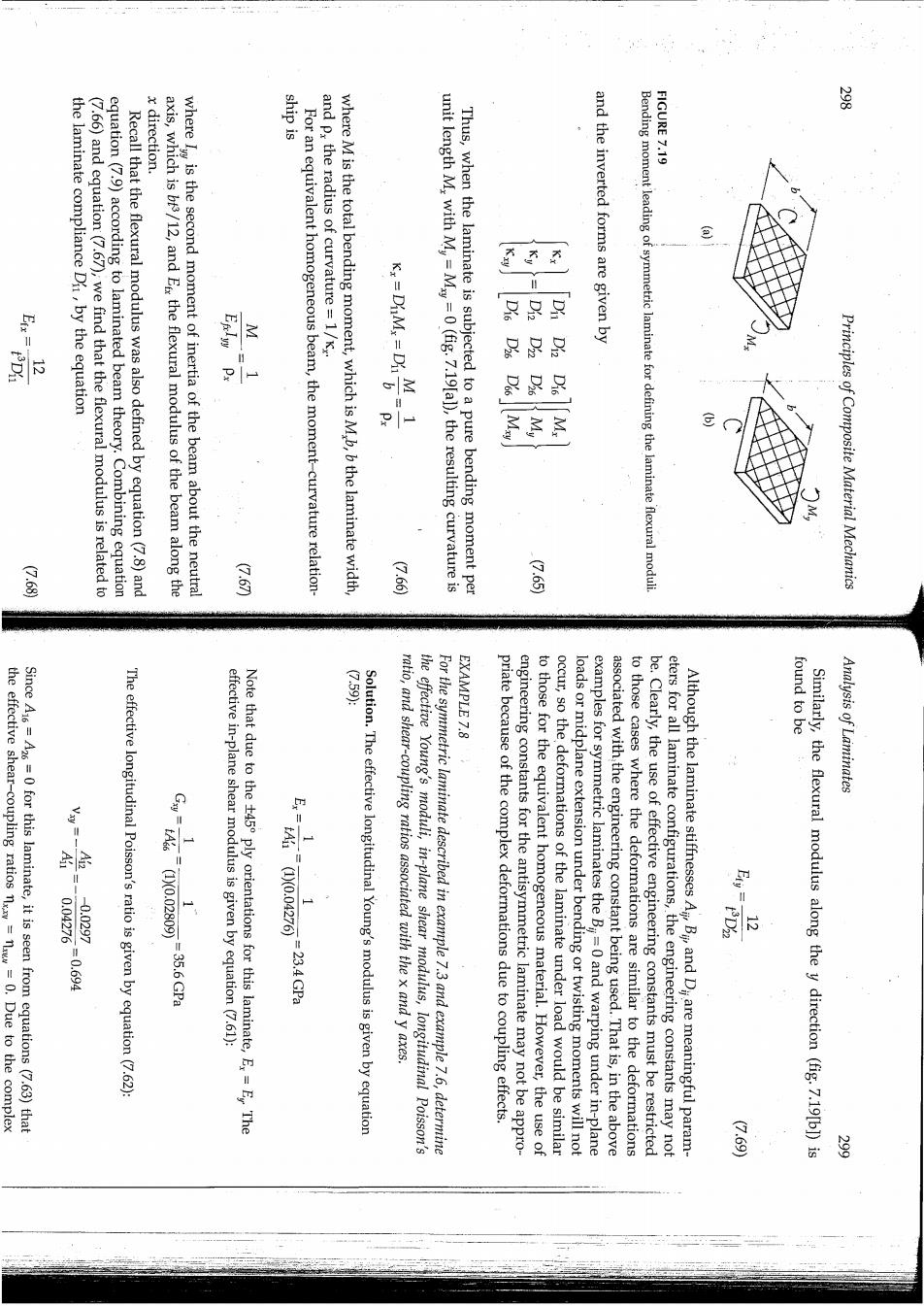
x direction. FIGURE 7.19 the laminate compliance Di,by the equation (7.66)and equation(7.67),we find that the flexural modulus is related to equation(7.9)according to laminated beam theory.Combining equation Recall that the flexural modulus was also defined by equation(7.8)and axis,which is bis/12,and E the flexural modulus of the beam along the where I is the second moment of inertia of the beam about the neutral For an equivalent homogeneous beam,the moment-curvature relation- /财:an where M is the total bending moment,which is M,b,b the laminate width, unit length M,with M=M=0(fig.7.19[al),the resulting curvature is Thus,when the laminate is subjected to a pure bending moment per and the inverted forms are given by Bending moment leading of symmetric laminate for defining the laminate flexural Principles of Composite Material Mechanics G.66 2.59. EXAMPLE 7.8 found to be the effective shear-coupling ratios nxxy=n=0.Due to the complex Since A16=A26=0 for this laminate,it is seen from equations (7.63)that I A 0.04276 -0.0297 -0.6g4 The effective longitudinal Poisson's ratio is given by equation(7.62): Fsn0.0000427 .35.6Gpa effective in-plane shear modulus is given by equation(7.61): Note that due to the t45 ply orientations for this laminate,Ex=E The =23.4 GPa Solution.The effective longitudinal Young's modulus is given by equation ratio,and shear-coupling ratios associated with the x and y axes. the effective Young's moduli,in-plane shear modulus,longitudinal Poisson's For the symmetric laminate described in example 7.3 and example 7.6,determine priate because of the complex deformations due to coupling effects. engineering constants for the antisymmetric laminate may not be appro- to those for the equivalent homogeneous material.However,the use of occur,so the deformations of the laminate under load would be similar loads or midplane extension under bending or twisting moments will not examples for symmetric laminates the Bi=0 and warping under in-plane associated with the engineering constant being used.That is,in the above to those cases where the deformations are similar to the deformations be.Clearly,the use of effective engineering constants must be restricted eters for all laminate configurations,the engineering constants may not Although the laminate stiffnesses A Bi,and Di are meaningful param- Similarly,the flexural modulus along the y direction (fig.7.19[b])is Analysis of Laminates (7.69)