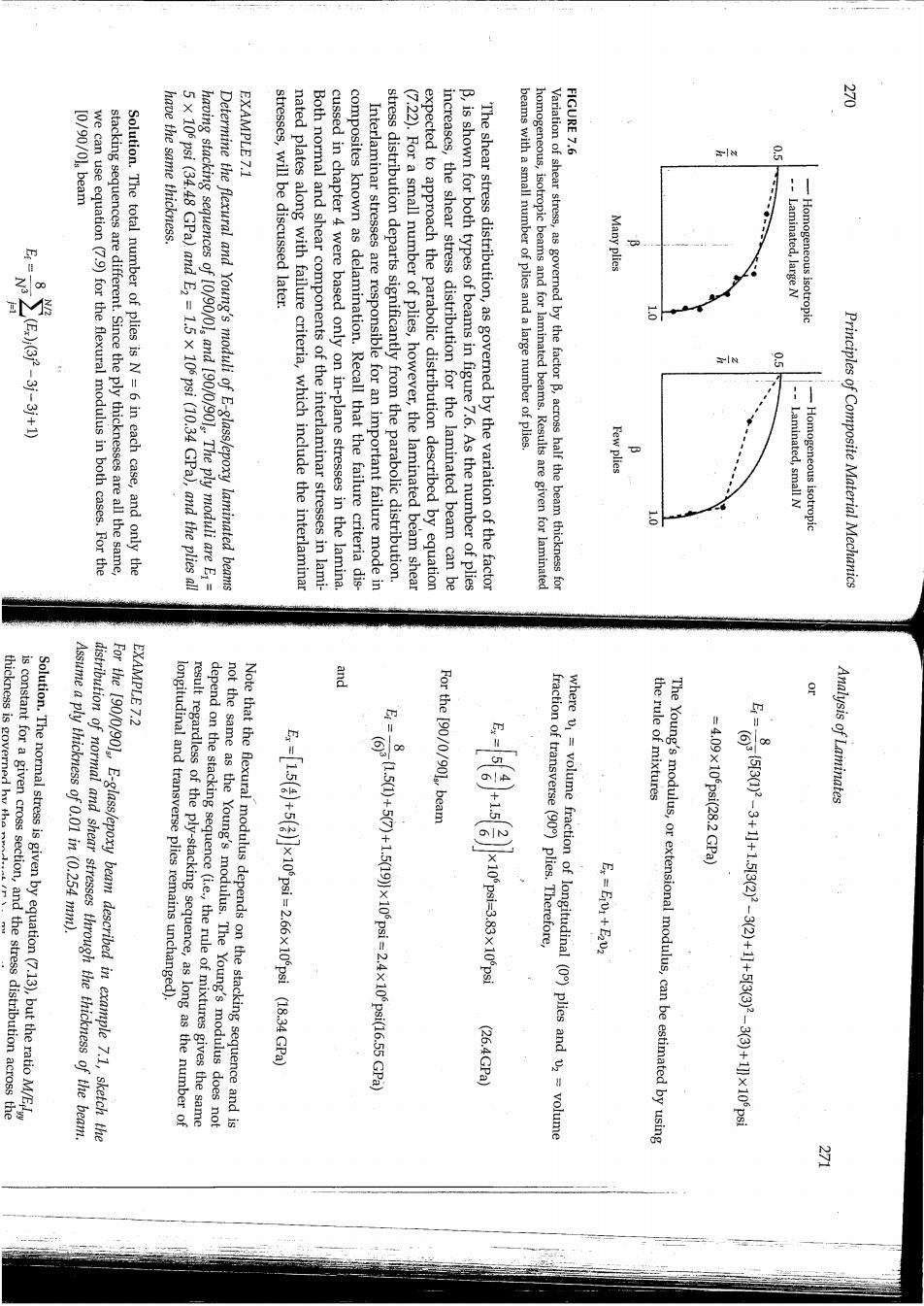
EXAMPLE 7.1 FIGURE 7.6 we can use equation (7.9)for the flexural modulus in both cases.For the stacking sequences are different.Since the ply thicknesses are all the same, Solution.The total number of plies is N=6 in each case,and only the have the same thickness. 5x 10⁶ psi (34.48 GPa).and E2=1.5 x 10⁶ psi (10.34 GPa),and the plies all having stacking sequences of [0/90/0]and [90/0/901 The ply moduli are E= Determine the flexural and Young's moduli of E-glass/epoxy laminated beams stresses,will be discussed later. nated plates along with failure criteria,which include the interlaminar Both normal and shear components of the interlaminar stresses in lami- cussed in chapter 4 were based only on in-plane stresses in the lamina. composites known as delamination.Recall that the failure criteria dis- Interlaminar stresses are responsible for an important failure mode in stress distribution departs significantly from the parabolic distribution. (7.22).For a small number of plies,however,the laminated beam shear expected to approach the parabolic distribution described by equation increases,the shear stress distribution for the laminated beam can be B,is shown for both types of beams in figure 7.6.As the number of plies The shear stress distribution,as governed by the variation of the factor beams with a small number of plies and a large number of plies. homogeneous,isotropic beams and for laminated beams.Results are given for laminated Variation of shear stress,as governed by the factor B,across half the beam thickness for Many plies Laminated,large N Homogeneous isotropic : Few plies -Laminated,small N -Homogeneous isotropic Principles of Composite Material Mechanics and thickness is governed hy the EXAMPLE 7.2 distribution of normal and shear stresses through the thickness of the beam. Assume a ply thickness of 0.01 in (0.254 mm). For the [90/0/90],E-glass/epoxy beam described in example 7.1,sketch the result regardless of the ply-stacking sequence,as long as the number of longitudinal and transverse plies remains unchanged). depend on the stacking sequence (i.e.,the rule of mixtures gives the same not the same as the Young's modulus.The Young's modulus does not Note that the flexural modulus depends on the stacking sequence and is For the [90/0/901,beam E=1.5(+5(x10psi=2.66x10psi (18.34 GPa) fraction of transverse(90)plies.Therefore, (26.4GPa) where v1=volume fraction of longitudinal (0)plies and v2 volume The Young's modulus,or extensional modulus,can be estimated by using the rule of mixtures =4.09x10psi(28.2 GPa) xR-H+Oe一++—多交法 Analysis of Laminates
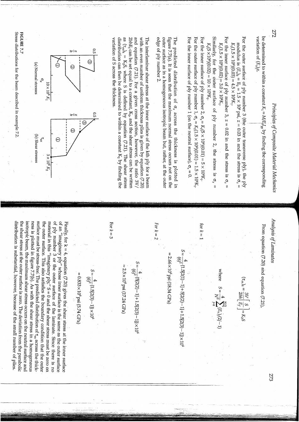
3 FIGURE 7.7 Stress distributions for the beam described in example 7.2. variation of S across the thickness. edge of ply number 2. k:(GX100(0.02)-10X104k: Kl.5X100/0.02-80x100k: K15X100)(008)-45X108k: variation of (E.)z. (a)Normal stresses 9 10.108X 品 (b)Shear stresses y distribution can then be determined to within a constant K2 by finding the as (T)k=K2S,where s is defined by equation (7.21).The shear stress 2bhEr can be set equal to a constant,K2 and the shear stress can be written and equation (7.21).For a given cross section,however,the ratio 3V/ with an even number of uniform thickness plies is given by equation(7.20) The interlaminar shear stress at the inner surface of the kth ply for a beam outer surface as in a homogeneous isotropic beam but,rather,at the outer figure 7.7(a).It is seen that the maximum normal stress occurs not on the The predicted distribution of o,across the thickness is plotted in For the inner surface of ply number 1 (on the neutral surface),,=0. :/k801X51-)100(0601X5。私1大:1 Fo For the inner surface of ply number 2,,=Ki(5x 10⁶)(0.01)=5x 10⁴K1. Similarly,for the outer surface of ply number 2,the stress is ox= For the inner surface of ply number 3,z=0.02 in and the stress is o,= modulus is (E )a=E2 =1.5 x 10⁶ psi,z=0.03 in and the stress is o,= For the outer surface of ply number 3(the outer transverse ply),the ply be determined to within a constant Ki=M/Eby finding the corresponding Principles of Composite Material Mechanics Fork=3 For k=2 for k=1 distribution is substantial,however,because of the small number of plies. the shear stress at the outer surface is zero.The deviation from the parabolic ness is plotted in figure 7.7(b).As with the shear stress in a homogeneous isotropic beam,the maximum shear stress occurs on the neutral surface and surface must be stress-free The predicted distribution ofacross the thick- the outer surface.This also satisfies the boundary condition that the outer material in this"imaginary ply,"S=0 and the shear stress must be zero on of ply number 3 or the outer surface of the laminate.Since there is no Finally,for k=4,equation(7.20)gives the shear stress at the inner surface of an"imaginary ply"whose inner surface is the same as the outer surface Analysis of Laminates -0.833x100pa1(6.74GRa :2.5X1022647.24GPa 装家 2166x100ps118.a4Gpa) 615((+1.5x10 兰 From equation(7.20)and equation(7.21)
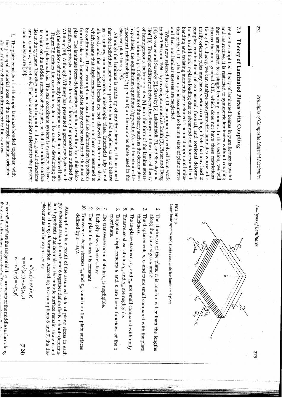
出 along arbitrary directions with respect to the xu axes. the principal material axes of the orthotropic laminae oriented 1.The plate consists of orthotropic laminae bonded together,with static analysis are [10]: are u,v,and w,respectively.The basic assumptions relevant to the present lies in the xy plane.The displacements at a point in thex,y,and z directions its origin on the middle surface of the plate,so that the middle surface laminated plate analysis.The xyz coordinate system is assumed to have Figure 7.8 defines the coordinate system to be used in developing the ing the equations of motion,only the static analysis will be considered here. Whitney [10].Although Whitney has presented a general analysis includ- mation hypothesis are now derived following the procedure outlined by plate.The laminate force-deformation equations resulting from this defor- from the classical homogeneous plate theory can be used for the laminated be continuous.These assumptions mean that the deformation hypothesis which means that displacements across lamina interfaces are assumed to allowed,and the interfacial bonds are not allowed to deform in shear, as a unitary,nonhomogeneous anisotropic plate.Interfacial slip is not that the individual laminae are perfectly bonded together so as to behave Although the laminate is made up of multiple laminae,it is assumed classical plate theory [9]. placement relationships(Appendix B)are the same as those used in the hypothesis,the equilibrium equations(Appendix A),and the strain-dis- strain relationships.Other elements of the theory such as the deformation of homogeneous,isotropic plates [9]is in the form of the lamina stress- Hoff [8].The major difference between this theory and the classical theory [41,Reissner and Stavsky [5],Stavsky [6],Lekhnitskii [7],and Stavsky and in the 1950s and 1960s by investigators such as Smith [31,Pister and Dong What is now referred to as the CLT has apparently evolved from work and that interlaminar stresses are neglected. tion of the CLT is that each ply is assumed to be in a state of plane stress bending and twisting moments are included.The most important limita- tions.In addition,in-plane loading due to shear and axial forces and both complex combinations of extensional,flexural,and torsional deforma- trarily oriented plies may have various coupling effects that may lead to Using this theory,we can analyze nonsymmetric laminates whose arbi- discuss the more general CLT,which does not have these restrictions. that are subjected to a single bending moment.In this section,we will and instructive,it is restricted to symmetric laminates without coupling While the simplified theory of laminated beams in pure flexure is useful Theory of Laminated Plates with Coupling Principles of Composite Material Mechanics the r and v dirertions placements can be expressed as thickness. FIGURE 7.8 where uand are the tangential displacements of the middle surface along normal during deformation.According to assumptions 6 and 7,the dis- coordinate. tion hypothesis that normals to the middle surface remain straight and ply,whereas assumptions 5 and 6 together define the Kirchhoff deforma- Assumption 5 is a result of the assumed state of plane stress in each 10.Transverse shear stresses Tand ty vanish on the plate surfaces defined by z=t/2. 9.The plate thickness t is constant. 8.Each ply obeys Hooke's law. The transverse normal strain e,is negligible. Tangential displacements u and v are linear functions of the 5.Transverse shear strains Y and Y are negligible. 4.The in-plane strains ey and Ysy are small compared with unity. The displacements u,v,and w are small compared with the plate along the plate edges,a and b. 2.The thickness of the plate,t,is much smaller than the lengths Coordinate system and stress resultants for laminated plate Analysis of Laminates (7.24)
and that 之 ment relations for the in-plane strains(Appendix B),we find that Substituting equations(7.24)and equations(7.27)in the strain-displace- functions of the z coordinate as follows: 是 笔 P0.0 20010 verse shear strains and using assumption 5,we find that (7.24)in the strain-displacement equations(Appendix B)for the trans- only develop the CLT based on equation (7.24).Substituting equations Such a theory is beyond the scope of this book,however,and we will which is based on the assumption that the displacements are nonlinear lamination theory.For example,Christensen [11]describes one such theory, transverse shear deformations,it is necessary to use a so-called higher-order for possible warping of the cross section of the laminate and resulting =w(x,y).At this point it is appropriate to mention that in order to account displacement of any point having the samex and y coordinates,so w(x,y) displacement at the middle surface,w(x,y),is the same as the transverse Principles of Composite Material Mechanics G28 国 G25 equations.Similarly,in the laminated plate analvsis the midlane related to the loads on the structure by additional static equilibrium stress,equation (7.13),was developed.The bending moment.can be ship in equation (7.4).The result was that a more useful equation for to the applied bending moment by using the static equilibrium relation- known and is difficult to measure.Thus,the lamina stress was related to be of limited practical use because the curvature is not generally In the laminated beam analysis,equation(7.3)for lamina stress is seen sion and shear.In addition,the laminated plate analysis includes the stresses due to shear coupling,as discussed in chapter 2. the laminated plate analysis gives the 2-D lamina stresses y and due to bending and twisting curvatures and to the midplane biaxial exten- only gives the uniaxial stress,ox,due to the bending curvature,whereas equation(7.3),we notice several differences.The laminated beam analysis plate stresses in equations(7.31)with the laminated beam stress given by where the subscript k refers to the kth lamina.Comparing the laminated before deformation. Analysis of Laminates 9 g relationships from equations (2.35)as follows: 9 第十 樂十茶 may be found by substituting equations(7.28)into the lamina stress-strain surface,the stresses along arbitrary xy axes in the kth lamina of a laminate Since equations(7.28)give the strains at any distance z from the middle with out-of-plane twisting of the middle surface,which lies in the xy plane the middle surface in the yz plane.K is a twisting curvature associated in the xz plane and K,is a bending curvature associated with bending of K,is a bending curvature associated with bending of the middle surface 1 and the curvatures of the middle surface are where the strains on the middle surface are 者 G50 G.29
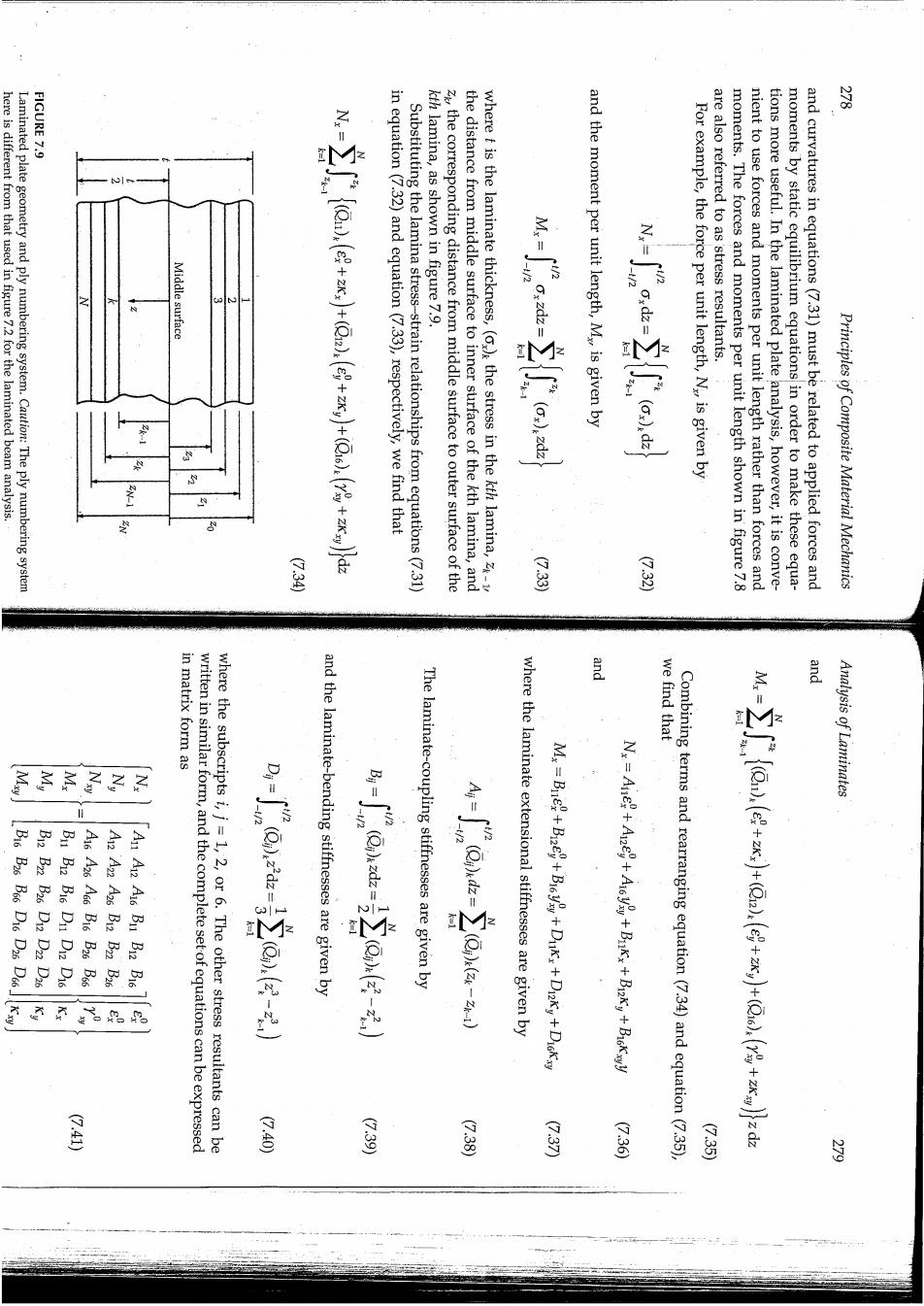
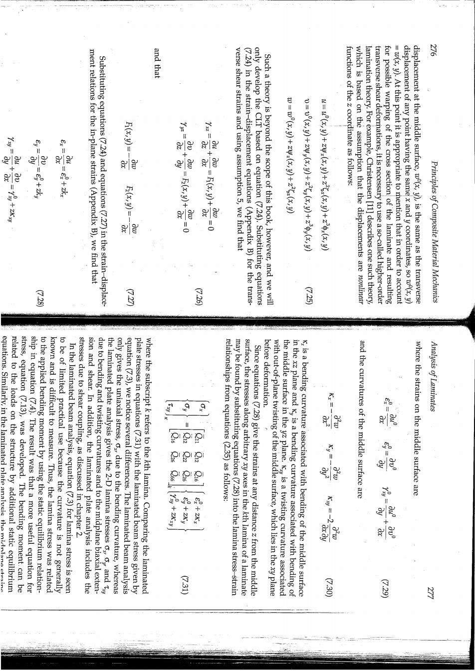
FIGURE 7.9 月 here is different from that used in figure 7.2 for the laminated beam analysis. Laminated plate geometry and ply numbering system.Caution:The ply numbering system Middle surface in equation (7.32)and equation(7.33),respectively,we find that Substituting the lamina stress-strain relationships from equations(7.31) kth lamina,as shown in figure 7.9. zk the corresponding distance from middle surface to outer surface of the the distance from middle surface to inner surface of the kth lamina,and where t is the laminate thickness,()the stress in the kth lamina,- and the moment per unit length,My is given by For example,the force per unit length,Na,is given by are also referred to as stress resultants. moments.The forces and moments per unit length shown in figure 7.8 nient to use forces and moments per unit length rather than forces and tions more useful.In the laminated plate analysis,however,it is conve- moments by static equilibrium equations in order to make these equa- and curvatures in equations(7.31)must be related to applied forces and Principles of Composite Material Mechanics 圣 是 是 in matrix form as 三 we find that and Analysis of Laminates 2 的 吧 4 0 君 and the laminate-bending stiffnesses are given by The laminate-coupling stiffnesses are given by 60 41/2402122 where the laminate extensional stiffnesses are given by 四 written in similar form,and the complete setof equations can be expressed where the subscripts i,j=1,2,or 6.The other stress resultants can be M:=Be+Bie+Bcy+Dukx+Dky+Diokxy Combining terms and rearranging equation(7.34)and equation(7.35) 4! G·c8 (7.37) G26 G35 三