accurately made. Components The following section provides information and specifications on all of the optical components included in the OS-9254A Complete Optics System,which includes all the components available from PASCO scientific.For a list of the components that are included in each PASCO optics system,see Table 2 in the Equipment section of the manual. NOTE:All the components in the PASCO optics system have been constructed to stand up under normal laboratory use.The holders are strong and the components,where possible,are recessed for protection.However,care should be taken to avoid touching or scratching the optical surfaces of all components. When cleaning components: Use a very soft cloth,or better yet,use lens tissue,for the optical surfaces. Use only alcohol or mild,soapy water as a cleaning agent.Other solvents may attack the plastic holders. Lenses and Mirrors All lenses are made of glass.The mirrors are made of front-surface, aluminumcoated glass.Lenses and mirrors are mounted in 50 x 50 mm acrylic holders,and are recessed to protect the optical surface.The type of component and its focal length(if it has one)is printed on the label on each holder. The available lenses and mirrors are listed in Table4. Table 4:Available Lenses and Mirrors Catalog Number Focal Length Type Table 5: Available Spectral Lenses: Filters 0S-9131 -22mm Concave Catalog Number Color 0S-9132 18mm Convex 0S-9111 Red 0S-9112 Yellow 0S-9133 48mm Convex 0S-9113 Green 0S-9134 127mm Convex 0S-9114 Blue 0S-9135 252mm Convex Mirrors: 0S-9136 N/A Flat 0S-9137 25mm Concave Spectral Filter(four slide) Four spectral filters are listed in Table 5. The spectrophotometric absorption curves for the filters are shown in Figure 14. ✉
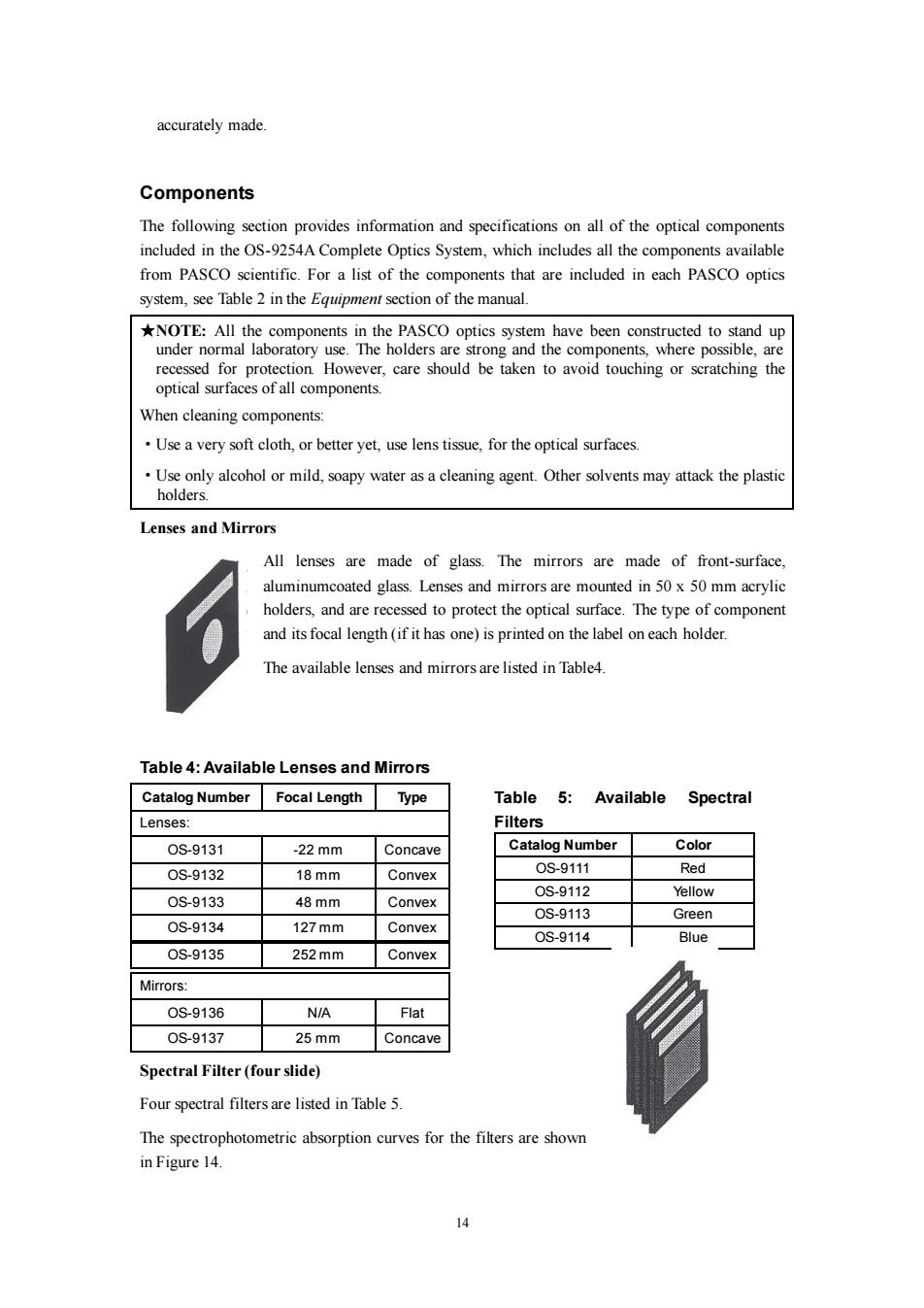
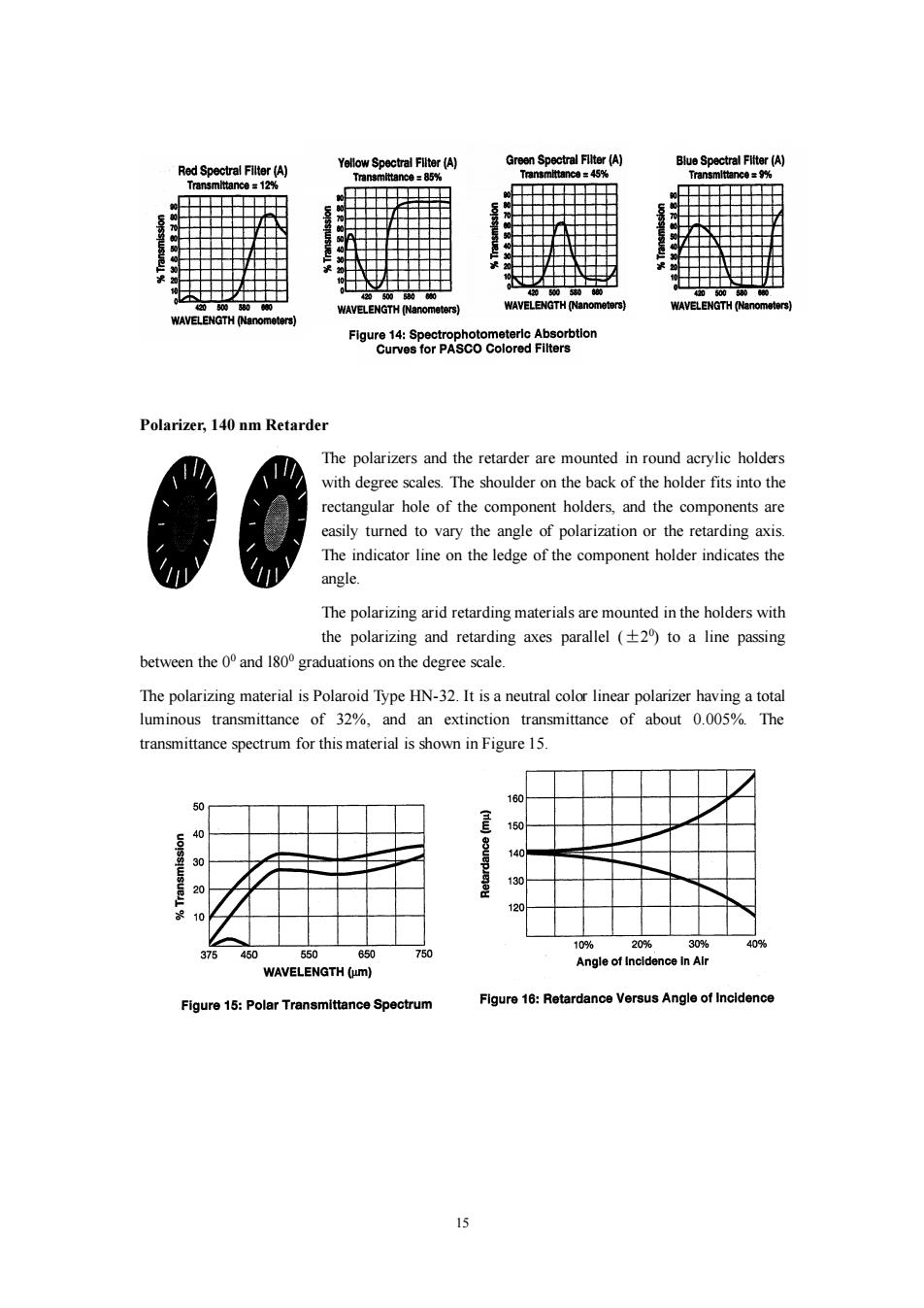
14 accurately made. Components The following section provides information and specifications on all of the optical components included in the OS-9254A Complete Optics System, which includes all the components available from PASCO scientific. For a list of the components that are included in each PASCO optics system, see Table 2 in the Equipment section of the manual. ★NOTE: All the components in the PASCO optics system have been constructed to stand up under normal laboratory use. The holders are strong and the components, where possible, are recessed for protection. However, care should be taken to avoid touching or scratching the optical surfaces of all components. When cleaning components: ·Use a very soft cloth, or better yet, use lens tissue, for the optical surfaces. ·Use only alcohol or mild, soapy water as a cleaning agent. Other solvents may attack the plastic holders. Lenses and Mirrors All lenses are made of glass. The mirrors are made of front-surface, aluminumcoated glass. Lenses and mirrors are mounted in 50 x 50 mm acrylic holders, and are recessed to protect the optical surface. The type of component and its focal length (if it has one) is printed on the label on each holder. The available lenses and mirrors are listed in Table4. Table 4: Available Lenses and Mirrors Catalog Number Focal Length Type Lenses: OS-9131 -22 mm Concave OS-9132 18 mm Convex OS-9133 48 mm Convex OS-9134 127 mm Convex OS-9135 252 mm Convex Mirrors: OS-9136 N/A Flat OS-9137 25 mm Concave Spectral Filter (four slide) Four spectral filters are listed in Table 5. The spectrophotometric absorption curves for the filters are shown in Figure 14. Table 5: Available Spectral Filters Catalog Number Color OS-9111 Red OS-9112 Yellow OS-9113 Green OS-9114 Blue
Green Spectral Fllter (A) Blue Spectral Fliter (A) Red Spectral Filter (A) Yellow Spectral Filter(A) Transmittance=85% Transmittance =45% Transmlttance =9% Transmlttance 12% 2 400580 00 0505800 WAVELENGTH (Nanometers) WAVELENGTH (Nanometers) WAVELENGTH (Nanometers) WAVELENGTH (Nanometers) Figure 14:Spectrophotometerlc Absorbtion Curves for PASCO Colored Filters Polarizer,140 nm Retarder The polarizers and the retarder are mounted in round acrylic holders with degree scales.The shoulder on the back of the holder fits into the rectangular hole of the component holders,and the components are easily turned to vary the angle of polarization or the retarding axis. The indicator line on the ledge of the component holder indicates the angle. The polarizing arid retarding materials are mounted in the holders with the polarizing and retarding axes parallel (+2)to a line passing between the 0 and 180 graduations on the degree scale. The polarizing material is Polaroid Type HN-32.It is a neutral color linear polarizer having a total luminous transmittance of 32%,and an extinction transmittance of about 0.005%.The transmittance spectrum for this material is shown in Figure 15. 160 50 40 30 30 20 10 10% 20% 30% 40% 375 450 550 650 750 Angle of Incldence In Alr WAVELENGTH (um) Figure 15:Polar Transmittance Spectrum Figure 16:Retardance Versus Angle of Incidence
15 Polarizer, 140 nm Retarder The polarizers and the retarder are mounted in round acrylic holders with degree scales. The shoulder on the back of the holder fits into the rectangular hole of the component holders, and the components are easily turned to vary the angle of polarization or the retarding axis. The indicator line on the ledge of the component holder indicates the angle. The polarizing arid retarding materials are mounted in the holders with the polarizing and retarding axes parallel (±2 0 ) to a line passing between the 00 and l800 graduations on the degree scale. The polarizing material is Polaroid Type HN-32. It is a neutral color linear polarizer having a total luminous transmittance of 32%, and an extinction transmittance of about 0.005%. The transmittance spectrum for this material is shown in Figure 15
The retardance of the retarder may be increased by varying the angle of incidence.Figure 16 shows the increase of retardance as a function of the incident angle.A good method for varying the angle is to mount the retarder in the special component carrier of the angular translator.By rotating the translator table,the angle of incidence can be accurately varied. *CAUTION:The surfaces of the polarizers and retarder are very easily scratched,and should be touched as little as possible.(The surfaces are cellulose acetate butyrate.) Glass Plate Size:50×50×6mm Refractive Index:1.518(at 588.9 nm) Acrylic Plate Size:50×50×19mm Refractive Index:1.48-1.50 Prism Angles::90°,450,450 Refractive Index:1.5 Material:BK-7Glass NOTE:the magnetic pads are strong enough to hold the prism with the steel base in a vertical position. Crossed-Arrow Target The crossed-arrow target is a useful object for object/image experiments.The fine lines on the horizontal arrow are a millimeter scale,which,when used in conjunction with the millimeter scale on the viewing screen,provides a convenient measure of magnification.The sharp edges and symmetrical shape are helpful for observing and analyzing spherical and chromatic aberration. Diffuser 16
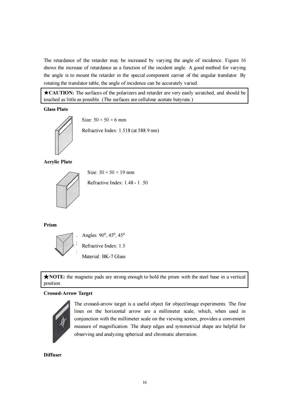
16 The retardance of the retarder may be increased by varying the angle of incidence. Figure 16 shows the increase of retardance as a function of the incident angle. A good method for varying the angle is to mount the retarder in the special component carrier of the angular translator. By rotating the translator table, the angle of incidence can be accurately varied. ★CAUTION: The surfaces of the polarizers and retarder are very easily scratched, and should be touched as little as possible. (The surfaces are cellulose acetate butyrate.) Glass Plate Size: 50 × 50 × 6 mm Refractive Index: 1.518 (at 588.9 nm) Acrylic Plate Size: 50 × 50 ×19 mm Refractive Index: 1.48 - 1 .50 Prism Angles: 900 , 450 , 450 Refractive Index: 1.5 Material: BK-7 Glass ★NOTE: the magnetic pads are strong enough to hold the prism with the steel base in a vertical position. Crossed-Arrow Target The crossed-arrow target is a useful object for object/image experiments. The fine lines on the horizontal arrow are a millimeter scale, which, when used in conjunction with the millimeter scale on the viewing screen, provides a convenient measure of magnification. The sharp edges and symmetrical shape are helpful for observing and analyzing spherical and chromatic aberration. Diffuser
The diffuser scatters light for experiments in which a relatively uniform illumination is required.The diffuser material is a thin sheet of acetate with a matte finish. Variable Diaphragm Aperture limits:1.25-10.0 mm Number of leaves:10 To vary the aperture,push the handle up or down. Light Source Apertures(two slides---OS-9118,OS-9119) Aperture widths:0.5,0.75 mm (OS-9118)1.0,2.0 mm(OS-9119) Use the light source apertures to collimate the light coming from the incandescent light source.You can place the slide on a component holder,or directly over the aperture of the light source. Photometer Apertures Aperture Widths:0.1,0.2,0.5,and 1.0 mm The photometer apertures can be used to vary the resolution of the fiber optic probe of the photometer.For accurate resolution,the tip of the optic probe must be flush against the aperture.This is most easily accomplished using the linear or angular translator as follows(see Figure 17). 1Place the aperture slide on the rear-most holder of the linear or angular translator Photometer iber-optic probe Apertures (the holder closest to the hole for the fiber-optic probe). 2Before inserting the probe,look through Linear the hole and position the aperture slide Translator so the desired aperture is centered in the Figure 17:Using the Photometer Apertures hole. Interference and Diffraction Apertures(4 slides- OS-9165A,B,C,and D) 3Insert the fiber-optic probe into the hole so that the tip is flush against the aperture. 17
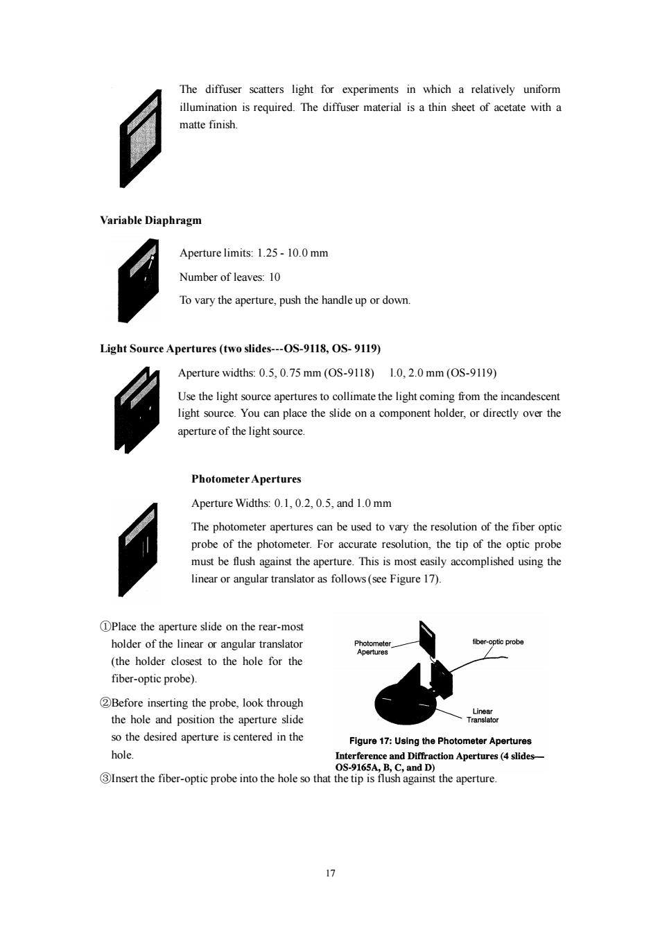
17 The diffuser scatters light for experiments in which a relatively uniform illumination is required. The diffuser material is a thin sheet of acetate with a matte finish. Variable Diaphragm Aperture limits: 1.25 - 10.0 mm Number of leaves: 10 To vary the aperture, push the handle up or down. Light Source Apertures (two slides---OS-9118, OS- 9119) Aperture widths: 0.5, 0.75 mm (OS-9118) l.0, 2.0 mm (OS-9119) Use the light source apertures to collimate the light coming from the incandescent light source. You can place the slide on a component holder, or directly over the aperture of the light source. Photometer Apertures Aperture Widths: 0.1, 0.2, 0.5, and 1.0 mm The photometer apertures can be used to vary the resolution of the fiber optic probe of the photometer. For accurate resolution, the tip of the optic probe must be flush against the aperture. This is most easily accomplished using the linear or angular translator as follows (see Figure 17). ①Place the aperture slide on the rear-most holder of the linear or angular translator (the holder closest to the hole for the fiber-optic probe). ②Before inserting the probe, look through the hole and position the aperture slide so the desired aperture is centered in the hole. ③Insert the fiber-optic probe into the hole so that the tip is flush against the aperture
Interference and Diffraction Apertures(4 slides---OS-9165A,B,C,D) Slide 1 (OS-9 165A):Four single slit apertures of different widths Slide 2(OS-9 165B):Four double slit apertures of different widths and slit spacing Slide 3(OS-9 165C):Four multiple slit apertures(2-5 slits),constant slit width and slit spacing Slide 4(OS-9165D):Two circular apertures and two aperture arrays Material:0.005 mm electroformed nickel Tolerances:±0.005mm This collection of 4 slides contains 16 slit and Patter A is a double slit pattern. Each slit is 0.04 mm wide,and the aperture patterns appropriate for interference distance between the two slits,from center to center,is 0.25 mm. and diffraction experiments.These aperture Pattern B is also a double slit patterns can be illuminated using either the pattem.Each slit is 0.04 mm wide, 1用 and the distance between the two incandescent light source or the laser. slits,from center to center,is 0.50 However,if you wish to project the mm. diffraction patterns onto the viewing screen, The dimensions of pattems C and D Slide 2 (OS-9165A) are determined similarily. the laser should be used. Figure 18:Slit Dimenslons Each slide is labeled with the dimensions of its four patterns.On each slide,the aperture patterns are labeled from A-D,with A corresponding to the leftmost pattern,and D corresponding to the right-most pattern. Slides 1-3 are for single,double,and multiple slit diffraction See Figure 18 for an explanation of the slit dimensions.Note:Slit Space,the spacing between slits,is measured from the center of one slit to the center of the adjacent slit. Slide 4 is for diffraction from circular apertures and aperture arrays.The diameter of the circular apertures,patterns A and B,are indicated on the slide (0.04 and 0.08 mm,respectively).The dimensions for the aperture arrays are shown in Figure 19. Slide4 (0S-9165D) 女 Patterns A and B are circular apertures: diameter A =0.04 mm diameter B-0.08 mm Pattern D Patterns C and D are shown to the right NOTE:The black areas above ×=0.025mm corre nd to the transparent y=0.075mm areas of the actual pattemns Figure 19:CIrcular Apertures and Aperture Arrays 伊
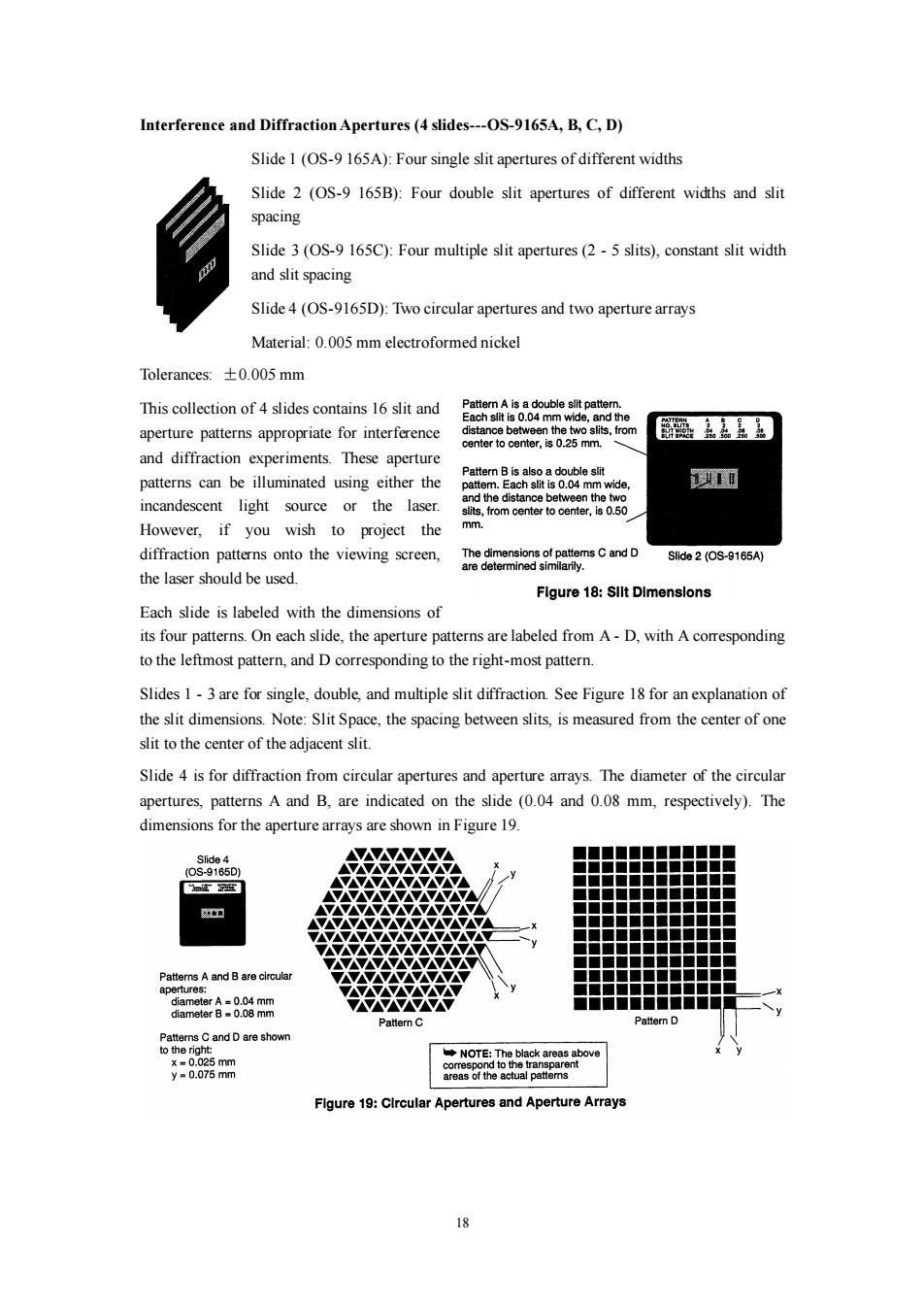
18 Interference and Diffraction Apertures (4 slides---OS-9165A, B, C, D) Slide 1 (OS-9 165A): Four single slit apertures of different widths Slide 2 (OS-9 165B): Four double slit apertures of different widths and slit spacing Slide 3 (OS-9 165C): Four multiple slit apertures (2 - 5 slits), constant slit width and slit spacing Slide 4 (OS-9165D): Two circular apertures and two aperture arrays Material: 0.005 mm electroformed nickel Tolerances: ±0.005 mm This collection of 4 slides contains 16 slit and aperture patterns appropriate for interference and diffraction experiments. These aperture patterns can be illuminated using either the incandescent light source or the laser. However, if you wish to project the diffraction patterns onto the viewing screen, the laser should be used. Each slide is labeled with the dimensions of its four patterns. On each slide, the aperture patterns are labeled from A - D, with A corresponding to the leftmost pattern, and D corresponding to the right-most pattern. Slides 1 - 3 are for single, double, and multiple slit diffraction. See Figure 18 for an explanation of the slit dimensions. Note: Slit Space, the spacing between slits, is measured from the center of one slit to the center of the adjacent slit. Slide 4 is for diffraction from circular apertures and aperture arrays. The diameter of the circular apertures, patterns A and B, are indicated on the slide (0.04 and 0.08 mm, respectively). The dimensions for the aperture arrays are shown in Figure 19