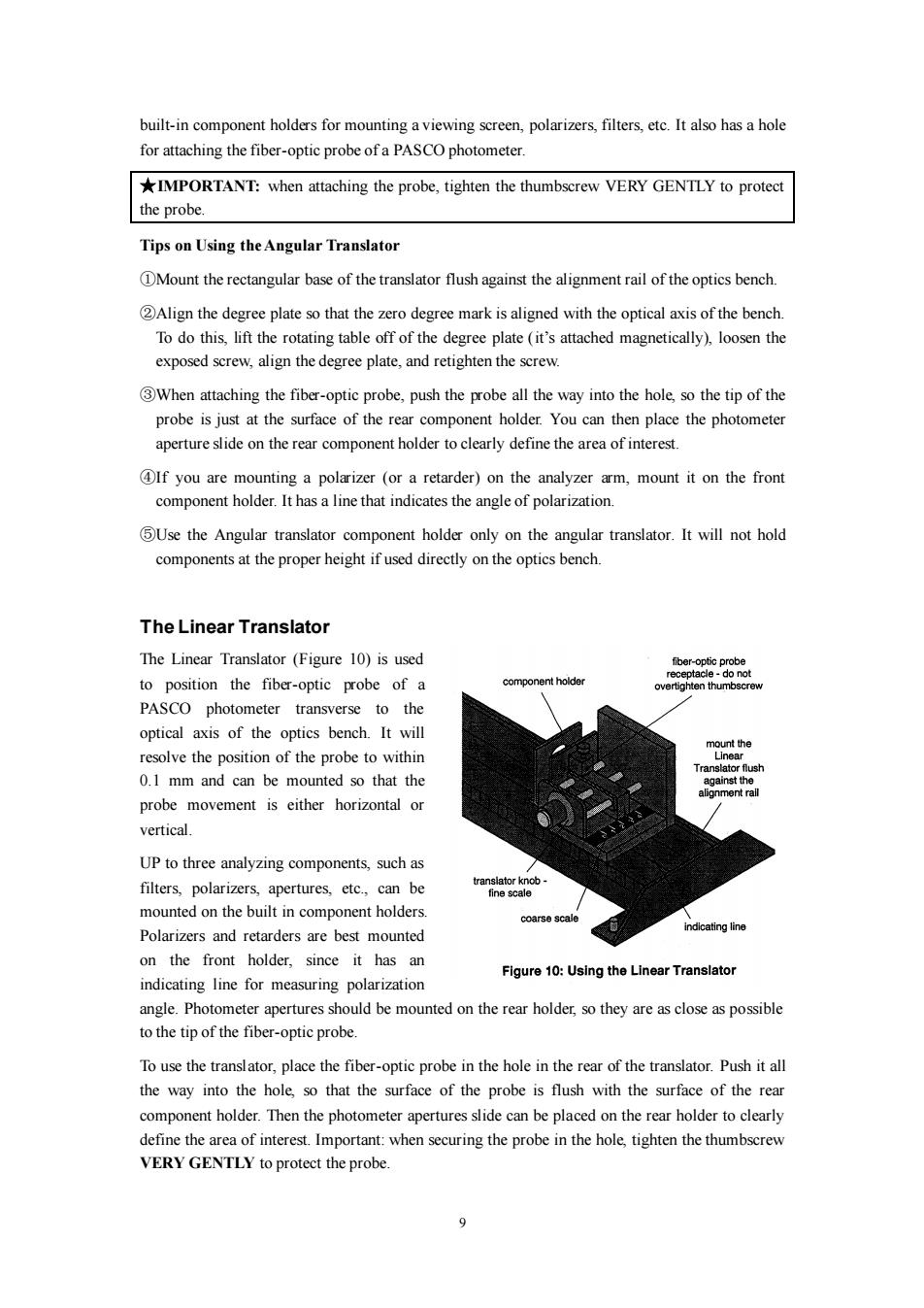
built-in component holders for mounting a viewing screen,polarizers,filters,etc.It also has a hole for attaching the fiber-optic probe of a PASCO photometer. *IMPORTANT:when attaching the probe,tighten the thumbscrew VERY GENTLY to protect the probe. Tips on Using the Angular Translator DMount the rectangular base of the translator flush against the alignment rail of the optics bench. Align the degree plate so that the zero degree mark is aligned with the optical axis of the bench. To do this,lift the rotating table off of the degree plate(it's attached magnetically),loosen the exposed screw,align the degree plate,and retighten the screw. 3When attaching the fiber-optic probe,push the probe all the way into the hole,so the tip of the probe is just at the surface of the rear component holder.You can then place the photometer aperture slide on the rear component holder to clearly define the area of interest OIf you are mounting a polarizer (or a retarder)on the analyzer arm,mount it on the front component holder.It has a line that indicates the angle of polarization. 5Use the Angular translator component holder only on the angular translator.It will not hold components at the proper height if used directly on the optics bench. The Linear Translator The Linear Translator (Figure 10)is used fiber-optic probe receptacle -do not to position the fiber-optic probe of a component holder overtighten thumbscrew PASCO photometer transverse to the optical axis of the optics bench.It will mount the resolve the position of the probe to within Linear Translator flush 0.1 mm and can be mounted so that the against the alignment rall probe movement is either horizontal or vertical. UP to three analyzing components,such as filters,polarizers,apertures,etc.,can be fine scale mounted on the built in component holders. coarse scale Polarizers and retarders are best mounted indicating line on the front holder,since it has an Figure 10:Using the Linear Translator indicating line for measuring polarization angle.Photometer apertures should be mounted on the rear holder,so they are as close as possible to the tip of the fiber-optic probe. To use the translator,place the fiber-optic probe in the hole in the rear of the translator.Push it all the way into the hole,so that the surface of the probe is flush with the surface of the rear component holder.Then the photometer apertures slide can be placed on the rear holder to clearly define the area of interest.Important:when securing the probe in the hole,tighten the thumbscrew VERY GENTLY to protect the probe
9 built-in component holders for mounting a viewing screen, polarizers, filters, etc. It also has a hole for attaching the fiber-optic probe of a PASCO photometer. ★IMPORTANT: when attaching the probe, tighten the thumbscrew VERY GENTLY to protect the probe. Tips on Using the Angular Translator ①Mount the rectangular base of the translator flush against the alignment rail of the optics bench. ②Align the degree plate so that the zero degree mark is aligned with the optical axis of the bench. To do this, lift the rotating table off of the degree plate (it’s attached magnetically), loosen the exposed screw, align the degree plate, and retighten the screw. ③When attaching the fiber-optic probe, push the probe all the way into the hole, so the tip of the probe is just at the surface of the rear component holder. You can then place the photometer aperture slide on the rear component holder to clearly define the area of interest. ④If you are mounting a polarizer (or a retarder) on the analyzer arm, mount it on the front component holder. It has a line that indicates the angle of polarization. ⑤Use the Angular translator component holder only on the angular translator. It will not hold components at the proper height if used directly on the optics bench. The Linear Translator The Linear Translator (Figure 10) is used to position the fiber-optic probe of a PASCO photometer transverse to the optical axis of the optics bench. It will resolve the position of the probe to within 0.1 mm and can be mounted so that the probe movement is either horizontal or vertical. UP to three analyzing components, such as filters, polarizers, apertures, etc., can be mounted on the built in component holders. Polarizers and retarders are best mounted on the front holder, since it has an indicating line for measuring polarization angle. Photometer apertures should be mounted on the rear holder, so they are as close as possible to the tip of the fiber-optic probe. To use the translator, place the fiber-optic probe in the hole in the rear of the translator. Push it all the way into the hole, so that the surface of the probe is flush with the surface of the rear component holder. Then the photometer apertures slide can be placed on the rear holder to clearly define the area of interest. Important: when securing the probe in the hole, tighten the thumbscrew VERY GENTLY to protect the probe
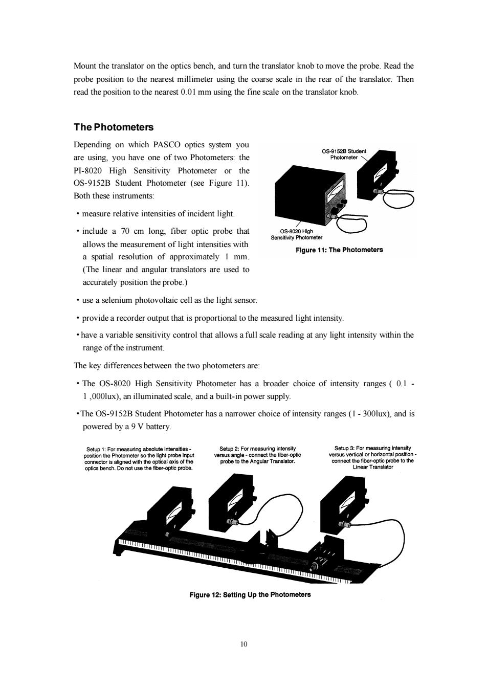
Mount the translator on the optics bench,and turn the translator knob to move the probe.Read the probe position to the nearest millimeter using the coarse scale in the rear of the translator.Then read the position to the nearest 0.01 mm using the fine scale on the translator knob. The Photometers Depending on which PASCO optics system you OS-9152B Student are using,you have one of two Photometers:the Photometer PI-8020 High Sensitivity Photometer or the OS-9152B Student Photometer (see Figure 11). Both these instruments: measure relative intensities of incident light. include a 70 cm long,fiber optic probe that OS-8020 High Sensitivity Photometer allows the measurement of light intensities with Flgure 11:The Photometers a spatial resolution of approximately 1 mm. (The linear and angular translators are used to accurately position the probe.) use a selenium photovoltaic cell as the light sensor. provide a recorder output that is proportional to the measured light intensity. have a variable sensitivity control that allows a full scale reading at any light intensity within the range of the instrument. The key differences between the two photometers are: The OS-8020 High Sensitivity Photometer has a broader choice of intensity ranges(0.1 1,000lux),an illuminated scale,and a built-in power supply. .The OS-9152B Student Photometer has a narrower choice of intensity ranges(1-300lux),and is powered by a 9 V battery. Setup 1:For measuring absolute intensities- Setup 2:For measuring intensity Setup 3:For measuring intensity position the Photometer so the light probe versus angle nect the fiber-optic versus vertical or horizontal position- connector is aligned with the optical axis of the probe to the Angular Translator connect the fiber-optic probe tohe optics bench.Do not use the fiber-optic probe. Linear Translator mmmmmmmmmmmmmmommmmmmmmmm Figure 12:Setting Up the Photometers 0
10 Mount the translator on the optics bench, and turn the translator knob to move the probe. Read the probe position to the nearest millimeter using the coarse scale in the rear of the translator. Then read the position to the nearest 0.01 mm using the fine scale on the translator knob. The Photometers Depending on which PASCO optics system you are using, you have one of two Photometers: the PI-8020 High Sensitivity Photometer or the OS-9152B Student Photometer (see Figure 11). Both these instruments: ·measure relative intensities of incident light. ·include a 70 cm long, fiber optic probe that allows the measurement of light intensities with a spatial resolution of approximately 1 mm. (The linear and angular translators are used to accurately position the probe.) ·use a selenium photovoltaic cell as the light sensor. ·provide a recorder output that is proportional to the measured light intensity. ·have a variable sensitivity control that allows a full scale reading at any light intensity within the range of the instrument. The key differences between the two photometers are: ·The OS-8020 High Sensitivity Photometer has a broader choice of intensity ranges ( 0.1 - 1 ,000lux), an illuminated scale, and a built-in power supply. ·The OS-9152B Student Photometer has a narrower choice of intensity ranges (1 - 300lux), and is powered by a 9 V battery
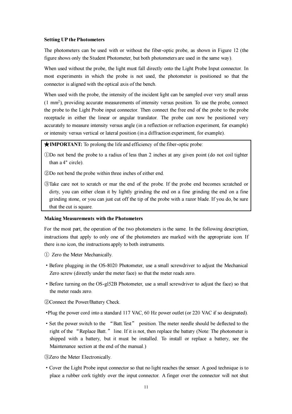
Setting UP the Photometers The photometers can be used with or without the fiber-optic probe,as shown in Figure 12 (the figure shows only the Student Photometer,but both photometers are used in the same way). When used without the probe,the light must fall directly onto the Light Probe Input connector.In most experiments in which the probe is not used,the photometer is positioned so that the connector is aligned with the optical axis of the bench. When used with the probe,the intensity of the incident light can be sampled over very small areas (1 mm2),providing accurate measurements of intensity versus position.To use the probe,connect the probe to the Light Probe input connector.Then connect the free end of the probe to the probe receptacle in either the linear or angular translator.The probe can now be positioned very accurately to measure intensity versus angle(in a reflection or refraction experiment,for example) or intensity versus vertical or lateral position(in a diffraction experiment,for example). *IMPORTANT:To prolong the life and efficiency of the fiber-optic probe: DDo not bend the probe to a radius of less than 2 inches at any given point(do not coil tighter than a 4"circle). 2Do not bend the probe within three inches of either end. 3Take care not to scratch or mar the end of the probe.If the probe end becomes scratched or dirty,you can either clean it by lightly grinding the end on a fine grinding the end on a fine grinding stone,or you can just cut off the tip of the probe with a razor blade.If you do,be sure that the cut is square. Making Measurements with the Photometers For the most part,the operation of the two photometers is the same.In the following description, instructions that apply to only one of the photometers are marked with the appropriate icon If there is no icon,the instructions apply to both instruments. 1 Zero the Meter Mechanically. Before plugging in the OS-8020 Photometer,use a small screwdriver to adjust the Mechanical Zero screw(directly under the meter face)so that the meter reads zero. Before turning on the OS-gl52B Photometer,use a small screwdriver to adjust the face)so that the meter reads zero. 2Connect the Power/Battery Check. .Plug the power cord into a standard 117 VAC,60 Hz power outlet (or 220 VAC if so designated). .Set the power switch to the "Batt.Test"position.The meter needle should be deflected to the right of the "Replace Batt."line.If it is not,then replace the battery (Note:The photometer is shipped with a battery,but it must be installed.To install or replace a battery,see the Maintenance section at the end of the manual.) 3Zero the Meter Electronically. Cover the Light Probe input connector so that no light reaches the sensor.A good technique is to place a rubber cork tightly over the input connector.A finger over the connector will not shut W
11 Setting UP the Photometers The photometers can be used with or without the fiber-optic probe, as shown in Figure 12 (the figure shows only the Student Photometer, but both photometers are used in the same way). When used without the probe, the light must fall directly onto the Light Probe Input connector. In most experiments in which the probe is not used, the photometer is positioned so that the connector is aligned with the optical axis of the bench. When used with the probe, the intensity of the incident light can be sampled over very small areas (1 mm2 ), providing accurate measurements of intensity versus position. To use the probe, connect the probe to the Light Probe input connector. Then connect the free end of the probe to the probe receptacle in either the linear or angular translator. The probe can now be positioned very accurately to measure intensity versus angle (in a reflection or refraction experiment, for example) or intensity versus vertical or lateral position (in a diffraction experiment, for example). ★IMPORTANT: To prolong the life and efficiency of the fiber-optic probe: ①Do not bend the probe to a radius of less than 2 inches at any given point (do not coil tighter than a 4" circle). ②Do not bend the probe within three inches of either end. ③Take care not to scratch or mar the end of the probe. If the probe end becomes scratched or dirty, you can either clean it by lightly grinding the end on a fine grinding the end on a fine grinding stone, or you can just cut off the tip of the probe with a razor blade. If you do, be sure that the cut is square. Making Measurements with the Photometers For the most part, the operation of the two photometers is the same. In the following description, instructions that apply to only one of the photometers are marked with the appropriate icon. If there is no icon, the instructions apply to both instruments. ① Zero the Meter Mechanically. ·Before plugging in the OS-8020 Photometer, use a small screwdriver to adjust the Mechanical Zero screw (directly under the meter face) so that the meter reads zero. ·Before turning on the OS-gl52B Photometer, use a small screwdriver to adjust the face) so that the meter reads zero. ②Connect the Power/Battery Check. ·Plug the power cord into a standard 117 VAC, 60 Hz power outlet (or 220 VAC if so designated). ·Set the power switch to the “Batt.Test” position. The meter needle should be deflected to the right of the “Replace Batt.” line. If it is not, then replace the battery (Note: The photometer is shipped with a battery, but it must be installed. To install or replace a battery, see the Maintenance section at the end of the manual.) ③Zero the Meter Electronically. ·Cover the Light Probe input connector so that no light reaches the sensor. A good technique is to place a rubber cork tightly over the input connector. A finger over the connector will not shut
out the light effectively enough.(Note:a finger over the input connector will shut out the light effectively enough for the less sensitive Student Photometer.). With the input connector covered,set the sensitivity Range switch to the most sensitive range, and turn the Zero Adjust knob until the meter reads zero.The instrument is now zeroed on all ranges.Now turn the sensitivity Range switch to the highest range. 4Measuring Relative intensities *IMPORTANT:The photometer reading is proportional to the energy of the light that falls on its photovoltaic cell,which is in turn proportional to the intensity of the incident light and to the area of the cell that is illuminated.Therefore,for accurate and consistent result,the incident light should fall directly onto the Light Probe Input connector or fiber-optic probe,with a zero degree angle of incidence. When using the photometers,intensity measurements are always made relative to some established reference value.If you were measuring the intensity of light after it passes through a polarized,for example,you would first measure the intensity of light for a particular orientation of the polarizer(usually,but not necessarily,the orientation producing a maximum intensity of light). When measuring this reference intensity,you would adjust the photometer sensitivity so that the meter read 10 (full scale).You could then measure the intensity for different orientations of the polarizer.These subsequent measurements would be recorded as a percentage of the original measurement.For example,if the meter read 6.5,you would record the intensive as 65%of the reference value. In general,to use the photometer to measure relative intensities: Arrange the photometer to measure your reference intensity,usually the maximum intensity of light that you expect to measure. Turn the sensitivity Range switch clockwise until the photometer reads off scale. Turn the sensitivity adjust knob counterclockwise until the meter reads exactly 10(full scale). Now-without touching the photometer controls arrange the photometer to measure the other intensities you wish to measure.Read the intensities as a percentage of the original measurement. NOTE:After measuring your reference intensity,you can use the sensitivity Range switch to change the range of the measurement.Just take into account the effect on the reading,as you would for any measuring instrument.For example,if the sensitivity Range switch were set to 100 when the reference source was measured,and then switched to 30,you would use the 0-3 scale and read your value as 0-30%.In a similar manner,if the sensitivity Range switch were turned to the 300 setting,you would use the 0-3 scale,and read your value as 0-300%. ⑤Output Jacks .A pair of output jacks are located on the back panel of the photometer.These jacks provide a voltage that is proportional to the meter reading.The voltage for a full-scale meter reading is 140 mV-10V@I mA,depending on the range selection.The recorder output voltage is independent of the setting of the Variable sensitivity knob. .A miniature phone jack is located on the front panel of the Model OS-9152B Photometer.This will provide approximate 1.5 V at 1 mA for a full-scale meter reading.Important:The recorder output voltage is independent of the setting of the Variable sensitivity knob. 白
12 out the light effectively enough. (Note: a finger over the input connector will shut out the light effectively enough for the less sensitive Student Photometer.). ·With the input connector covered, set the sensitivity Range switch to the most sensitive range, and turn the Zero Adjust knob until the meter reads zero. The instrument is now zeroed on all ranges. Now turn the sensitivity Range switch to the highest range. ④Measuring Relative intensities ★IMPORTANT: The photometer reading is proportional to the energy of the light that falls on its photovoltaic cell, which is in turn proportional to the intensity of the incident light and to the area of the cell that is illuminated. Therefore, for accurate and consistent result, the incident light should fall directly onto the Light Probe Input connector or fiber-optic probe, with a zero degree angle of incidence. When using the photometers, intensity measurements are always made relative to some established reference value. If you were measuring the intensity of light after it passes through a polarized, for example, you would first measure the intensity of light for a particular orientation of the polarizer (usually, but not necessarily, the orientation producing a maximum intensity of light). When measuring this reference intensity, you would adjust the photometer sensitivity so that the meter read 10 (full scale). You could then measure the intensity for different orientations of the polarizer. These subsequent measurements would be recorded as a percentage of the original measurement. For example, if the meter read 6.5, you would record the intensive as 65% of the reference value. In general, to use the photometer to measure relative intensities: ·Arrange the photometer to measure your reference intensity, usually the maximum intensity of light that you expect to measure. ·Turn the sensitivity Range switch clockwise until the photometer reads off scale. ·Turn the sensitivity adjust knob counterclockwise until the meter reads exactly 10 (full scale). ·Now-without touching the photometer controls arrange the photometer to measure the other intensities you wish to measure. Read the intensities as a percentage of the original measurement. NOTE: After measuring your reference intensity, you can use the sensitivity Range switch to change the range of the measurement. Just take into account the effect on the reading, as you would for any measuring instrument. For example, if the sensitivity Range switch were set to 100 when the reference source was measured, and then switched to 30, you would use the 0-3 scale and read your value as 0-30%. In a similar manner, if the sensitivity Range switch were turned to the 300 setting, you would use the 0-3 scale, and read your value as 0-300%. ⑤Output Jacks. ·A pair of output jacks are located on the back panel of the photometer. These jacks provide a voltage that is proportional to the meter reading. The voltage for a full-scale meter reading is 140 mV - 10 V @ 1 mA, depending on the range selection. The recorder output voltage is independent of the setting of the Variable sensitivity knob. ·A miniature phone jack is located on the front panel of the Model OS-9152B Photometer. This will provide approximate 1.5 V at 1 mA for a full-scale meter reading. Important: The recorder output voltage is independent of the setting of the Variable sensitivity knob
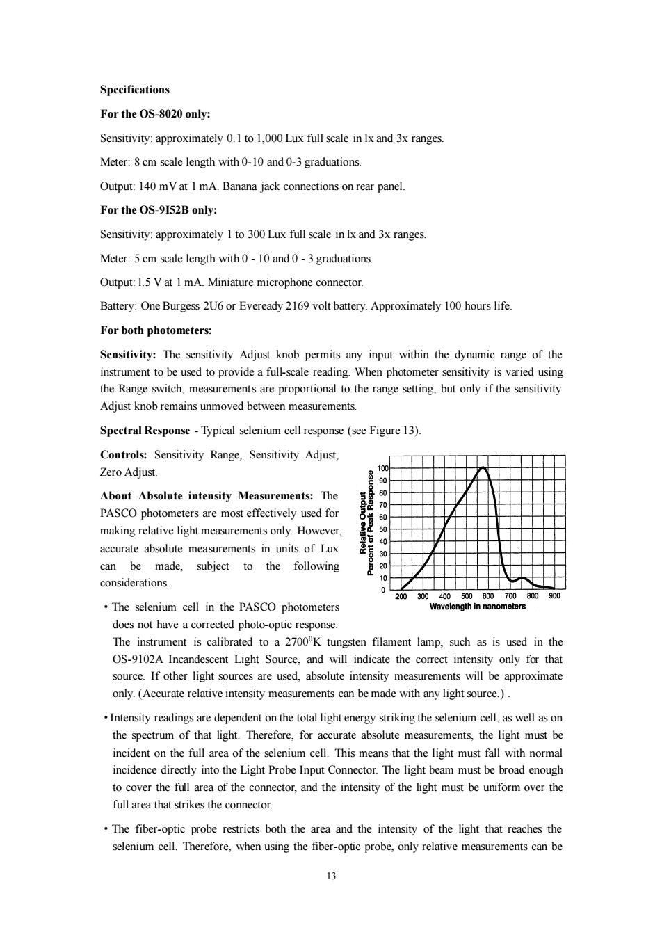
Specifications For the OS-8020 only: Sensitivity:approximately 0.1 to 1,000 Lux full scale in Ix and 3x ranges. Meter:8 cm scale length with 0-10 and 0-3 graduations Output:140 mV at 1 mA.Banana jack connections on rear panel. For the OS-9152B only: Sensitivity:approximately I to 300 Lux full scale in Ix and 3x ranges. Meter:5 cm scale length with 0-10 and 0-3 graduations. Output:1.5 V at 1 mA.Miniature microphone connector. Battery:One Burgess 2U6 or Eveready 2169 volt battery.Approximately 100 hours life. For both photometers: Sensitivity:The sensitivity Adjust knob permits any input within the dynamic range of the instrument to be used to provide a full-scale reading.When photometer sensitivity is varied using the Range switch,measurements are proportional to the range setting,but only if the sensitivity Adjust knob remains unmoved between measurements. Spectral Response-Typical selenium cell response(see Figure 13). Controls:Sensitivity Range,Sensitivity Adjust, Zero Adjust. 100 About Absolute intensity Measurements:The 80 70 PASCO photometers are most effectively used for 60 making relative light measurements only.However. 50 accurate absolute measurements in units of Lux 40 30 can be made,subject to the following considerations. 0 200300400500600700800900 The selenium cell in the PASCO photometers Wavelength In nanometers does not have a corrected photo-optic response. The instrument is calibrated to a 2700K tungsten filament lamp,such as is used in the OS-9102A Incandescent Light Source,and will indicate the correct intensity only for that source.If other light sources are used,absolute intensity measurements will be approximate only.(Accurate relative intensity measurements can be made with any light source.). Intensity readings are dependent on the total light energy striking the selenium cell,as well as on the spectrum of that light.Therefore,for accurate absolute measurements,the light must be incident on the full area of the selenium cell.This means that the light must fall with normal incidence directly into the Light Probe Input Connector.The light beam must be broad enough to cover the full area of the connector,and the intensity of the light must be uniform over the full area that strikes the connector. The fiber-optic probe restricts both the area and the intensity of the light that reaches the selenium cell.Therefore,when using the fiber-optic probe,only relative measurements can be 3
13 Specifications For the OS-8020 only: Sensitivity: approximately 0.1 to 1,000 Lux full scale in lx and 3x ranges. Meter: 8 cm scale length with 0-10 and 0-3 graduations. Output: 140 mV at 1 mA. Banana jack connections on rear panel. For the OS-9I52B only: Sensitivity: approximately 1 to 300 Lux full scale in lx and 3x ranges. Meter: 5 cm scale length with 0 - 10 and 0 - 3 graduations. Output: l.5 V at 1 mA. Miniature microphone connector. Battery: One Burgess 2U6 or Eveready 2169 volt battery. Approximately 100 hours life. For both photometers: Sensitivity: The sensitivity Adjust knob permits any input within the dynamic range of the instrument to be used to provide a full-scale reading. When photometer sensitivity is varied using the Range switch, measurements are proportional to the range setting, but only if the sensitivity Adjust knob remains unmoved between measurements. Spectral Response - Typical selenium cell response (see Figure 13). Controls: Sensitivity Range, Sensitivity Adjust, Zero Adjust. About Absolute intensity Measurements: The PASCO photometers are most effectively used for making relative light measurements only. However, accurate absolute measurements in units of Lux can be made, subject to the following considerations. ·The selenium cell in the PASCO photometers does not have a corrected photo-optic response. The instrument is calibrated to a 27000K tungsten filament lamp, such as is used in the OS-9102A Incandescent Light Source, and will indicate the correct intensity only for that source. If other light sources are used, absolute intensity measurements will be approximate only. (Accurate relative intensity measurements can be made with any light source.) . ·Intensity readings are dependent on the total light energy striking the selenium cell, as well as on the spectrum of that light. Therefore, for accurate absolute measurements, the light must be incident on the full area of the selenium cell. This means that the light must fall with normal incidence directly into the Light Probe Input Connector. The light beam must be broad enough to cover the full area of the connector, and the intensity of the light must be uniform over the full area that strikes the connector. ·The fiber-optic probe restricts both the area and the intensity of the light that reaches the selenium cell. Therefore, when using the fiber-optic probe, only relative measurements can be