Part3 Effects of Earthquakes on Structure 3-1 SEISMIC DAMAGE(地震破坏) Structural damage due to an earthquake is not solely a function of the earthquake ground motion.The primary factors affecting the extent of damage are: Earthquake characteristics,such as (a)peak ground acceleration,(b)duration of strong shaking.(c)frequency content,and(d)length of fault rupture Site characteristics,such as(a)distance between the epicenter and structure,(b) geology between the epicenter and structure,(c)soil conditions at the site,and (d) natural period of the site. Structural characteristics,such as(a)natural period and damping of the structure, (b)age and construction method of the structure,and (c)seismic provisions (i.e. detailing)included in the design 3-2 SEISMIC Risk Zone(地震危险地带 In order to design a structure to withstand the effects of an earthquake.it is necessary to determine the expected earthquake magnitude.While extensive mathematical models could be developed for each location,seismic codes have evolved a simplified model based on seismic zones.The seismic zone map referenced by the 1997 Uniform Building Code is shown in Fig3.1 There are several methods of evaluating the significance of the seismic risk zones.One method is to correlate the zones with the approximate accelerations and magnitudes, as Table3.1 does. Another interpretation of the significance of the zones is to correlate then to the effects of an earthquake and the Modified Mercalli intensity scale as in Table 3.2 3-3 RISK MICROZONES(局部地晨危险区) Certain limited areas,referred to as microzones,consistently experience higher ground accelerations than do surround areas.This tendency is primarily attributed to the site (ie.,soil)conditions in the microzone,as the soil profile affects the peak ground acceleration,frequency content,and duration of strong motion.Inasmuch as seismic damage is at least partially related to ground acceleration,knowledge of such microzonification is essential.The microzonification concept,however,has not been explicitly incorporated in the Uniform Building Code,although it is implicit in the design process Mexico City has incorporated microzones into its rebuilding plan following the devastating earthquake in 1985.Considering the significant variations in damage in
Part3 Effects of Earthquakes on Structure 3-1 SEISMIC DAMAGE(地震破坏) Structural damage due to an earthquake is not solely a function of the earthquake ground motion. The primary factors affecting the extent of damage are: Earthquake characteristics, such as (a) peak ground acceleration,(b) duration of strong shaking, (c) frequency content, and (d) length of fault rupture Site characteristics, such as (a) distance between the epicenter and structure, (b) geology between the epicenter and structure, (c) soil conditions at the site, and (d) natural period of the site. Structural characteristics, such as (a) natural period and damping of the structure, (b) age and construction method of the structure, and (c) seismic provisions (i.e., detailing) included in the design 3-2 SEISMIC Risk Zone(地震危险地带) In order to design a structure to withstand the effects of an earthquake,it is necessary to determine the expected earthquake magnitude.While extensive mathematical models could be developed for each location,seismic codes have evolved a simplified model based on seismic zones. The seismic zone map referenced by the 1997 Uniform Building Code is shown in Fig.3.1. There are several methods of evaluating the significance of the seismic risk zones.One method is to correlate the zones with the approximate accelerations and magnitudes, as Table3.1 does. Another interpretation of the significance of the zones is to correlate then to the effects of an earthquake and the Modified Mercalli intensity scale as in Table 3.2 3-3 RISK MICROZONES(局部地震危险区) Certain limited areas, referred to as microzones, consistently experience higher ground accelerations than do surround areas. This tendency is primarily attributed to the site (i.e.,soil) conditions in the microzone, as the soil profile affects the peak ground acceleration, frequency content, and duration of strong motion. Inasmuch as seismic damage is at least partially related to ground acceleration, knowledge of such microzonification is essential. The microzonification concept, however, has not been explicitly incorporated in the Uniform Building Code, although it is implicit in the design process. Mexico City has incorporated microzones into its rebuilding plan following the devastating earthquake in 1985. Considering the significant variations in damage in

different areas of San Francisco Bay Area during the Loma Prieta earthquake, microzonification has also been widely proposed.(For example,unreinforced buildings in Chinatown where not damaged,while similarly constructed buildings in the Marina district were.Portions of the Cypress structure onclay collapsed,but other portions built on firmer soil did not.) 3-6 SITE PERIOD(场地土周期) The site (soil)period is now recognized as a significant factor contributing to structural damage.When a site has a natural frequency of vibration that corresponds to the predominant earthquake frequency,site movement can be greatly magnified.This is known as resonance.(see sec.4-13.)Thus,the buildings can experience ground motion much greater than would be predicted from only the seismic energy release. Determining the actual site period is no easy matter.Since the site period can be computed precisely from widely available formulas and still be grossly inaccurate, such determinations are best left to experts familiar with the area. Other soil characteristics,including density ,bearing strength,moisture content, compressibility(ie.,tendency to settle )and Sensitivity (ie.,tendency to liquefy), are additional factors not addressed by the seismic code.These factors, nevertheless,must be considered in structure design
different areas of San Francisco Bay Area during the Loma Prieta earthquake, microzonification has also been widely proposed. (For example, unreinforced buildings in Chinatown where not damaged, while similarly constructed buildings in the Marina district were. Portions of the Cypress structure on clay collapsed, but other portions built on firmer soil did not.) 3-6 SITE PERIOD (场地土周期) The site(soil)period is now recognized as a significant factor contributing to structural damage.When a site has a natural frequency of vibration that corresponds to the predominant earthquake frequency, site movement can be greatly magnified.This is known as resonance.(see sec.4-13.)Thus,the buildings can experience ground motion much greater than would be predicted from only the seismic energy release. Determining the actual site period is no easy matter.Since the site period can be computed precisely from widely available formulas and still be grossly inaccurate, such determinations are best left to experts familiar with the area. Other soil characteristics,including density ,bearing strength,moisture content , compressibility(i.e.,tendency to settle ),and Sensitivity (i.e.,tendency to liquefy), are additional factors not addressed by the seismic code.These factors , nevertheless ,must be considered in structure design
Part 4 VIBRATION THEORY 4.1 TWO APPROACHES TOSEISMIC DESIGN There are two greatly different approaches to seismic design,both of which are"correct"in their own ways.In a dynamic analysis,the overall building and story stiffnesses and rigidities are calculated.(c4-)Aspecific design and oading history.is selected and applied toa mathematical model(consisting of lumped masses,damping.and spring stiffness)of the building.The solution may rest heavily on vibrational theory,finite element analysis,and other advanced structural techniques requiring computer analysis.The response of the system (including the displacement and acceleration functions)is calculated and used to determine the forces in each member as a function of time This method is now almost always There are a number of factors that can render the dynamic approach inappropriate.The building itself may be too simple or too standardized to warrant the rigorous approach of the design analysis.Conversely,the building may be too complex and have too many degrees of freedom to model mathematically.Also,in the initial design phases,the member sizes and locati and rigidities The pproach is inappropriate.too.when the design earthquake is not known.Addiy nam analysis may be beyond the financial or computational abilities of the engineering fim performing the design.And,finally,unless the building is particularly irregular as defined in UBC-97Sec.1629.5.3,there may be no code requirement to perform a dynamic analysis. analysis so that there is no need to know the design earthquake. In the chapters and sections that follow,these two methods are at times discussed separately and,at other times aspects of each method are combined.Although considerably different in roach,the statie method is baed on engineering logic that can,in many cases,be traced back 4-2 SIMPLE HARMONIC MOTION Ideal vibrational systems that consist of springs and masses and that are not acted upon by external disturbing forces(after an initial displacement)are known as simple harmonic oscillators During y cillat ve in a repetitive sin ttern known motion Simp harmonic motion is by the absenc disturbing force and a lack of frictional damping. Examples of simple harmonic oscillators are a mass hanging on an ideal spring(Fig 4.1(a)) a pendulum on a frictionless pivot and a slab supported on two massless cantilever springs(fig.4.1(b). The number of variables needed to define the position of all parts of a system is known as its degrees of freedom.If the oscllator is constrained tomove in one dimension ony,or alternatively if one linear or angular variable is sufficient to describe the position of the oscillator,the system is known as a single-degree-of-freedom (SDOF)system.The moving mass in an SDOF system is usually concentrated at one point and is known as a lumped mass
Part4 VIBRATION THEORY 4.1 TWO APPROACHES TO SEISMIC DESIGN There are two greatly different approaches to seismic design, both of which are ”correct” in their own ways .In a dynamic analysis , the overall building and story stiffnesses and rigidities are calculated.(See Sec.4-4) A specific design earthquake, including magnitude and loading history, is selected and applied to a mathematical model(consisting of lumped masses, damping, and spring stiffness) of the building. The solution may rest heavily on vibrational theory, finite element analysis, and other advanced structural techniques requiring computer analysis. The response of the system (including the displacement and acceleration functions) is calculated and used to determine the forces in each member as a function of time. This method is now almost always used for critical structures such as dams and power plants. There are a number of factors that can render the dynamic approach inappropriate. The building itself may be too simple or too standardized to warrant the rigorous approach of the design analysis. Conversely, the building may be too complex and have too many degrees of freedom to model mathematically. Also, in the initial design phases, the member sizes and locations may not be known, making it difficult to estimate stiffnesses and rigidities. The dynamic approach is inappropriate, too, when the design earthquake is not known. Additionally, the analysis may be beyond the financial or computational abilities of the engineering firm performing the design. And, finally, unless the building is particularly irregular as defined in UBC-97Sec.1629.5.3, there may be no code requirement to perform a dynamic analysis. The alternative to a dynamic analysis is a static analysis. The equivalent lateral (seismic)force is calculated as simply some fraction of the dead weight.Chapter16of the UBC-97 codifies this analysis so that there is no need to know the design earthquake. In the chapters and sections that follow, these two methods are at times discussed separately and, at other times ,aspects of each method are combined. Although considerably different in approach, the static method is based on engineering logic that can ,in many cases, be traced back to vibration theory. 4-2 SIMPLE HARMONIC MOTION Ideal vibrational systems that consist of springs and masses and that are not acted upon by external disturbing forces (after an initial displacement) are known as simple harmonic oscillators. During steady-state motion, such oscillators move in a repetitive sinusoidal pattern known as simple harmonic motion. Simple harmonic motion is characterized by the absence of a continued disturbing force and a lack of frictional damping. Examples of simple harmonic oscillators are a mass hanging on an ideal spring ( Fig.4.1(a) ), a pendulum on a frictionless pivot, and a slab supported on two massless cantilever springs(fig.4.1(b). The number of variables needed to define the position of all parts of a system is known as its degrees of freedom. If the oscillator is constrained to move in one dimension only, or alternatively, if one linear or angular variable is sufficient to describe the position of the oscillator, the system is known as a single-degree-of –freedom (SDOF) system . The moving mass in an SDOF system is usually concentrated at one point and is known as a lumped mass

Oscillation of the SDOF system shown in Fig4.2 is initiated by displacing and releasing the mass. displaced and rele set in motion,the mass remains in motion indefinitely. 4-3 STIFFNESS AND FLEXIBILITY When fore.F.Hooke's law predicts the of the the force that must be applied in order to deflect hr spring a distance of one unit F=kd Hooke'slaw] [4.1 Referring to the mass-spring system shown in Fig4.1(a),the spring is undeflected until the static deflection. Wmgkx [us][4.2(a) g。 W=mg=kx [S[4.2b) The stiffness,k.of a beam can be calculated as the ratio of applied force to deflection from the beam deflection tables that are typically in every mechanics of materials textbook.Table4.1 summarizes some of these terms. Compliance (flexibility)is the reciprocal of stiffness.It is the deflection obtained when a unit force is applied.Therefore,its units are(m/N). 4-4 RIGIDITY Strictly speaking,rigidity,R,is the reciprocal of deflection In buildings where all members consist of the same material and all walls have the same thickness (for example.a masonry-walled building or an all-concrete building),the deflection is traditionally calculated with arbitrary values applied lateral loads to vertical members because the load "taken"by each member is proportional to the member'srelative rigidity. 1 R= [U.S.][(a)] R-254 [S4.3b Xwm Both moment and shear contribute to the deflection experienced by a vertical member(e.g.a shear wall)Consider the wall sh in Fig)Thisll a the top and botom and bends in double urvature since the top and bottom must reman vertical Such a wall is knownas a fixed pier.The deflection due to both shear and flexure of a fixed pier is giver by Eq.4.4
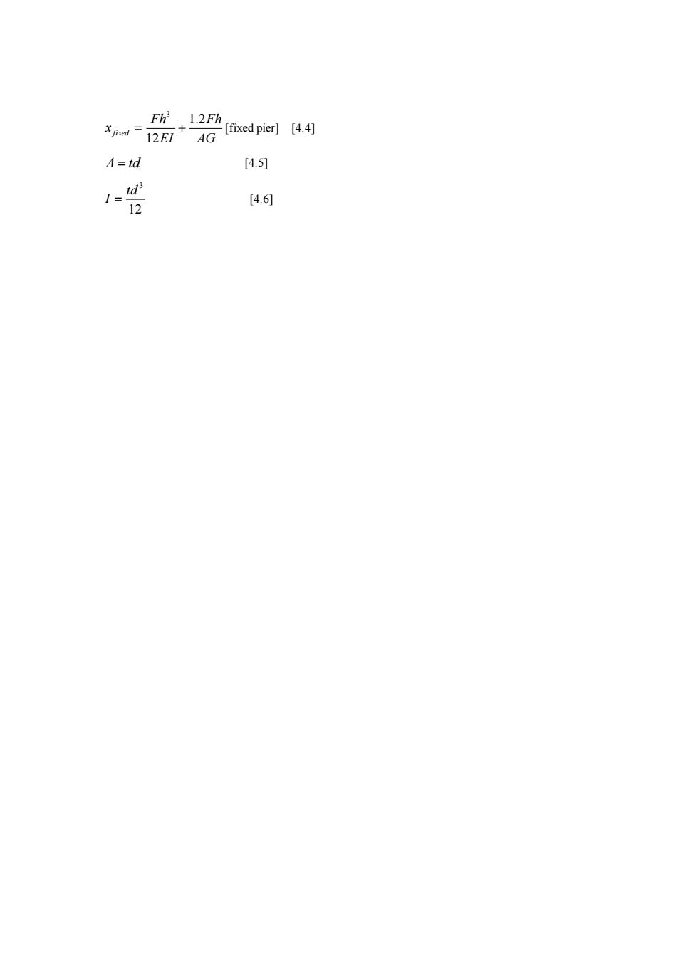
Oscillation of the SDOF system shown in Fig.4.2 is initiated by displacing and releasing the mass. The displacement, x ,is measured from the equilibrium position. Once the system has been displaced and released, no further external force acts on it. Because there is no friction once it is set in motion, the mass remains in motion indefinitely. 4-3 STIFFNESS AND FLEXIBILITY When a force, F, acts on an ideal linear spring, Hooke’s law predicts the magnitude of the spring deflection, x. In Eq.4.1, k is the stiffness or spring constant in 1bf/ft (N/m). The stiffness is the force that must be applied in order to deflect hr spring a distance of one unit. F = kx[Hooke'slaw] [4.1] Referring to the mass-spring system shown in Fig.4.1(a), the spring is undeflected until the mass is attached to it. After the mass is attached, the spring will deflect an amount known as the static deflection. st c kx g mg W = = [u.s.] [4.2(a)] st W = mg = kx [SI] [4.2(b)] The stiffness, k, of a beam can be calculated as the ratio of applied force to deflection from the beam deflection tables that are typically in every mechanics of materials textbook.Table4.1 summarizes some of these terms. Compliance(flexibility) is the reciprocal of stiffness. It is the deflection obtained when a unit force is applied. Therefore, its units are ft/lbf (m/N). 4-4 RIGIDITY Strictly speaking, rigidity, R, is the reciprocal of deflection. In buildings where all members consist of the same material and all walls have the same thickness (for example, a masonry-walled building or an all-concrete building), the deflection is traditionally calculated with arbitrary values of applied force, modulus of elasticity, and wall thickness. This is permitted when distributing the applied lateral loads to vertical members because the load ”taken” by each member is proportional to the member’s relative rigidity. inches x R 1 = [U.S.] [(a)] mm x R 25.4 = [SI] [4.3(b)] Both moment and shear contribute to the deflection experienced by a vertical member(e.g., a shear wall).Consider the wall shown in Fig.4.3(a). This wall is fixed at the top and bottom and bends in double curvature since the top and bottom must remain vertical. Such a wall is known as a fixed pier. The deflection due to both shear and flexure of a fixed pier is giver by Eq.4.4
1(fixed pier 12E1 AG A=Id 4.5) 12 [4.6
AG Fh EI Fh xfixed 1.2 12 3 = + [fixed pier] [4.4] A = td [4.5] 12 3 td I = [4.6]