
7.2.2 Inductor Geometries Figure 7.9.Various inductor structures:(a)circular,(b)octagonal,(c)symmetric,(d)stacked,(e)with grounded shield,(f) parallel spirals. [View full size imagel (b) (e) M9 M9 M6 Broken M8 Shield M7 e (0
7.2.2 Inductor Geometries
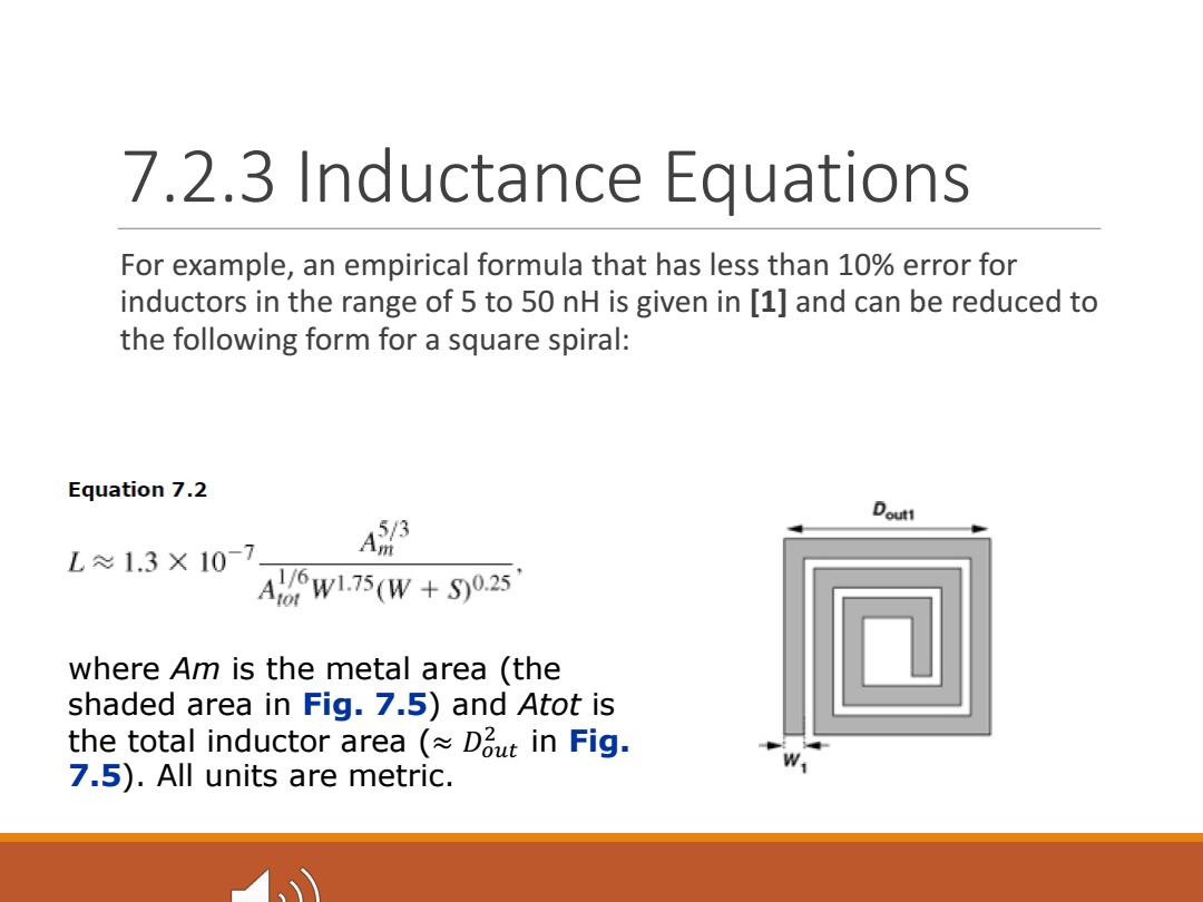
7.2.3 Inductance Equations For example,an empirical formula that has less than 10%error for inductors in the range of 5 to 50 nH is given in [1]and can be reduced to the following form for a square spiral: Equation 7.2 A3 Doutt L≈1.3×10- Aw6w175(W+S0.25 where Am is the metal area (the shaded area in Fig.7.5)and Atot is the total inductor area Dout in Fig. 7.5).All units are metric
7.2.3 Inductance Equations For example, an empirical formula that has less than 10% error for inductors in the range of 5 to 50 nH is given in [1] and can be reduced to the following form for a square spiral: where Am is the metal area (the shaded area in Fig. 7.5) and Atot is the total inductor area (≈ �!"# $ in Fig. 7.5). All units are metric

Figure 7.10.Spiral inductor for calculation of line length. G The metal area is thus given by Equation 7.13,7.14 M Am W[4NDout 4N2W-(2N-1)2S] 4NW[Dout -W-(N -1)(W S)]. Dout An interesting property of inductors is that,for a given wire length,width,and spacing,their inductance is a weak function of the number of turns. Equation 7.15 L≈1.3×10⁻⁷ 1/3 ltot 4N +W+(W-1)(W+S) w0.083(W+S0.25
An interesting property of inductors is that, for a given wire length, width, and spacing, their inductance is a weak function of the number of turns

For example,if /tot 2000 um,W=4 um,and S=0.5 um, then as N varies from 2 to 3 to 4 to 5,then inductance rises from 3.96 nH to 4.47 nH to 4.83 nH to 4.96 nH,respectively. In other words,a given length of wire yields roughly a constant inductance regardless of how it is "wound." The key point here is that,since this length has a given series resistance (at low frequencies),the choice of N only mildly affects the Q(but can save area). But the number of turns must be at least 2 to create mutual coupling. Figure 7.11.Inductance as a function of the number of turns for a given line length. 5.0 4.5 (Hu)7 4.0- 3.0时 3456N 260180142120110Dout(um)
For example, if ltot = 2000 µm, W = 4 µm, and S = 0.5 µm, then as N varies from 2 to 3 to 4 to 5, then inductance rises from 3.96 nH to 4.47 nH to 4.83 nH to 4.96 nH, respectively. In other words, a given length of wire yields roughly a constant inductance regardless of how it is “wound.” The key point here is that, since this length has a given series resistance (at low frequencies), the choice of N only mildly affects the Q (but can save area). But the number of turns must be at least 2 to create mutual coupling
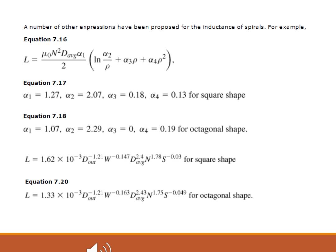
A number of other expressions have been proposed for the inductance of spirals.For example, Equation 7.16 L=LoN2Davga 2 (g+asn+ap) Equation 7.17 a1=1.27,2=2.07,3=0.18,u4=0.13 for square shape Equation 7.18 1.07,a2 2.29,3 =0,a4 =0.19 for octagonal shape. L=1.62X 10-D2W-0.147DN7-0.03 for square shape Equation 7.20 L=1.331-D2W-0.163DN1.75s-0049 for octagonal shape