
8 Appendix 8.1 Procedure of MCCEFF Input File Preparation The instructions described below deal with the preparing of input data file to the MCCEFF analysis in the case there is no need to use the mesh generator. 1.Heading line (12a4)general information 2.General information about the problem homogenised(6i5) Column Variable Description 1-5 NUMNP Total number of nodal point in the structure discretised 6-10 NELTYP Total number of finite element groups(=1) 11-15 LL Total number of load cases (=3) 36-40 KEQB Total number of non-zero degrees of freedom in the main matrix 66-70 MK Total number of random trials 71-75 NBN Total number of nodal points of the interfaces General comments: A.NELTYP variable is provided due to the original POLSAP code to extend in the next version the MCCEFF code with the analysis of the engineering structures homogenised (e.g.fibre-reinforced plates and shells).However due to its constant value it may have been omitted. B.LL variable is provided taking into account that in the next versions of the program the rest of the effective tensor components will be computed (in the 3D homogenisation problem).There are three different components of the elasticity tensor homogenised for the plane strain problems being solved by the program. C.KEQB parameter should be modified (default value is equal to 0)if the program MCCEFF in the process of main stiffness matrix formation or solution of the fundamental algebraic equations system stops running.The value of the parameter is to be taken from the interval [O,NEQB].where NEQB is the total number of the degrees of freedom of the composite cell.The probability of the successful computations increases with decreasing KEQB parameter
8 Appendix 8.1 Procedure of MCCEFF Input File Preparation The instructions described below deal with the preparing of input data file to the MCCEFF analysis in the case there is no need to use the mesh generator. 1. Heading line (12a4) general information 2. General information about the problem homogenised (6i5) Column Variable Description 1-5 NUMNP Total number of nodal point in the structure discretised 6-10 NELTYP Total number of finite element groups (=1) 11-15 LL Total number of load cases (=3) 36-40 KEQB Total number of non-zero degrees of freedom in the main matrix 66-70 MK Total number of random trials 71-75 NBN Total number of nodal points of the interfaces General comments: A. NELTYP variable is provided due to the original POLSAP code to extend in the next version the MCCEFF code with the analysis of the engineering structures homogenised (e.g. fibre-reinforced plates and shells). However due to its constant value it may have been omitted. B. LL variable is provided taking into account that in the next versions of the program the rest of the effective tensor components will be computed (in the 3D homogenisation problem). There are three different components of the elasticity tensor homogenised for the plane strain problems being solved by the program. C. KEQB parameter should be modified (default value is equal to 0) if the program MCCEFF in the process of main stiffness matrix formation or solution of the fundamental algebraic equations system stops running. The value of the parameter is to be taken from the interval [0,NEQB], where NEQB is the total number of the degrees of freedom of the composite cell. The probability of the successful computations increases with decreasing KEQB parameter

Appendix 383 3.Nodal points data (7i5,4d10.0,3i2) Column Variable Description 2-5 N Nodal point number 7-10 X(N,1) 11-15 XN,2) 16-20 XN,3) Displacement boundary conditions codes 21-25 XN,4) =0,free degree of freedom 26-30 N,5) =1,fixed degree of freedom 31-35 XN,6) 36-45 X(N) X coordinate 46-55 Y(N) Y coordinate 56-65 Z(N) Z coordinate 66-70 K(N) Nodal point generation code 71-72 MI Number of the internal region 73-74 M2 Number of the external region 75-77 M3 The interface end code (=1) General comments: A.Nodal point numbering has to be continuous and to start from number 1,which should denote the centre of the fibre (considering stress boundary conditions computations). B.Interface nodal points numbering has to be provided in the anticlockwise system and the distances between any two points must be equal. C.The structure being discretised should be placed in the YZ plane;the X coordinate will be used in the next version for the analysis of the 3D composite problems. D.The regions of the different materials should have increasing number starting from the central component (fibre in two-component composites)and continuous to the external boundary of the cell. E.In the case of half or quarter of the periodicity cell analysis the M3 parameter should be used to underline the ends of the interface being cutted. 4.General finite elements data (3i5) Column Variable Description 1-5 =3 Plane strain code 6-10 NUMEL Total number of finite elements 11-15 NUMMAT Total number of composite components
Appendix 383 3. Nodal points data (7i5,4d10.0,3i2) Column Variable Description 2-5 N Nodal point number 7-10 IX(N,1) 11-15 IX(N,2) 16-20 IX(N,3) Displacement boundary conditions codes 21-25 IX(N,4) =0, free degree of freedom 26-30 IX(N,5) =1, fixed degree of freedom 31-35 IX(N,6) 36-45 X(N) X coordinate 46-55 Y(N) Y coordinate 56-65 Z(N) Z coordinate 66-70 K(N) Nodal point generation code 71-72 M1 Number of the internal region 73-74 M2 Number of the external region 75-77 M3 The interface end code (=1) General comments: A. Nodal point numbering has to be continuous and to start from number 1, which should denote the centre of the fibre (considering stress boundary conditions computations). B. Interface nodal points numbering has to be provided in the anticlockwise system and the distances between any two points must be equal. C. The structure being discretised should be placed in the YZ plane; the X coordinate will be used in the next version for the analysis of the 3D composite problems. D. The regions of the different materials should have increasing number starting from the central component (fibre in two-component composites) and continuous to the external boundary of the cell. E. In the case of half or quarter of the periodicity cell analysis the M3 parameter should be used to underline the ends of the interface being cutted. 4. General finite elements data (3i5) Column Variable Description 1-5 =‘3’ Plane strain code 6-10 NUMEL Total number of finite elements 11-15 NUMMAT Total number of composite components

384 Random Composites 5.Material data 5.1.General data (2i5,2d10.0) Column Description 1-5 Material number 6-10 Total number of different temperatures 11-20 Gravity loading 21-30 Mass density General comment: The total number of the materials used should be greater than 10. 5.2.Detailed data two lines for any different temperature(8d10.0/3d10.0) Column Description 1-10 Temperature 11-20 Elasticity modulus E 21-30 Elasticity modulus E 31-40 Elasticity modulus E, 41-50 Poisson coefficient y 51-60 Poisson coefficient y, 61-70 Poisson coefficient y, 71-80 Shear modulus G 1-10 Coefficient of thermal expansion 11-20 Coefficient of thermal expansion a, 21-30 Coefficient of thermal expansion a
384 Random Composites 5. Material data 5.1. General data (2i5,2d10.0) Column Description 1-5 Material number 6-10 Total number of different temperatures 11-20 Gravity loading 21-30 Mass density General comment: The total number of the materials used should be greater than 10. 5.2. Detailed data two lines for any different temperature (8d10.0/3d10.0) Column Description 1-10 Temperature 11-20 Elasticity modulus En 21-30 Elasticity modulus Es 31-40 Elasticity modulus Et 41-50 Poisson coefficient nn 51-60 Poisson coefficient ns 61-70 Poisson coefficient nt 71-80 Shear modulus G 1-10 Coefficient of thermal expansion an 11-20 Coefficient of thermal expansion as 21-30 Coefficient of thermal expansion at
Appendix 385 6.Probabilistic parameters(2d10.0/2i5,4d10.0) Column Description 1-10 Variance of Young modulus 11-20 Variance of Poisson ratio 1-5 Averaged material type: =1,material without defects =2,material with interface defects =3,material with volume defects 6-10 Structural defects type: =1.circle =2,triangle =3,rectangle =4,hexagon 11-20 Expected value of the geometrical parameter 21-30 Variance of the geometrical parameter 31-40 Expected value of defects total number 41-50 Variance of defects total number 7.Finite elements description(7i5) Column Description 1-5 Finite element number 6-10 I node number 11-15 J node number 16-20 K node number 21-25 L node number 26-30 Material number 56-60 Finite elements generation code: =0(default)-the lack of generation =1,generation 8.2 Input Data for ABAQUS Reinforced Concrete Plate Analysis Example input data file for the ABAQUS [1]analysis of the steel reinforced concrete plate analysed in the book.The comment lines are indicated by '*to
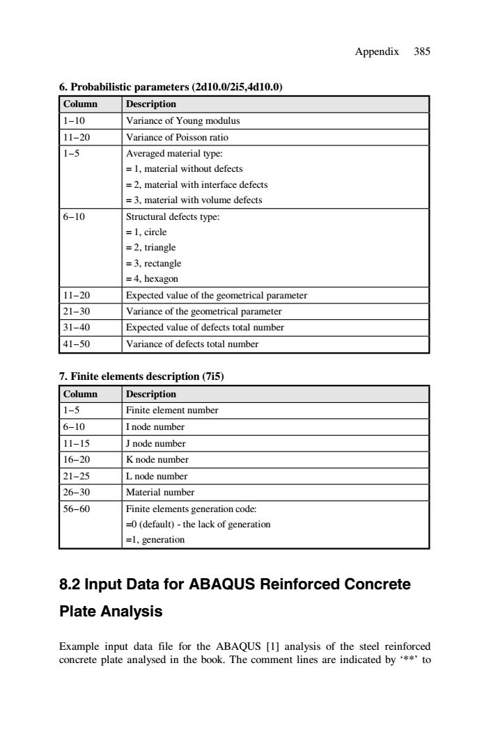
Appendix 385 6. Probabilistic parameters (2d10.0/2i5,4d10.0) Column Description 1-10 Variance of Young modulus 11-20 Variance of Poisson ratio 1-5 Averaged material type: = 1, material without defects = 2, material with interface defects = 3, material with volume defects 6-10 Structural defects type: = 1, circle = 2, triangle = 3, rectangle = 4, hexagon 11-20 Expected value of the geometrical parameter 21-30 Variance of the geometrical parameter 31-40 Expected value of defects total number 41-50 Variance of defects total number 7. Finite elements description (7i5) Column Description 1-5 Finite element number 6-10 I node number 11-15 J node number 16-20 K node number 21-25 L node number 26-30 Material number 56-60 Finite elements generation code: =0 (default) - the lack of generation =1, generation 8.2 Input Data for ABAQUS Reinforced Concrete Plate Analysis Example input data file for the ABAQUS [1] analysis of the steel reinforced concrete plate analysed in the book. The comment lines are indicated by ‘**’ to
386 Random Composites enable the user to gain a better understanding of model computed.The lines indicated by*or without any indication are program execution lines. *heading corner supported shell **all material and geometrical parameters are defined in US units *node 1,0.0. 7,18.,0. 61.0.18. 67,18.,18. *node numbers,their coordinates *ngen,nset=y-sym 1,7 *node generation on the 'y-sym'boundary with numbers from I to 7 *ngen,nset=x-sym 1.61,10 *node generation on the 'x-sym'boundary with numbers from 1 to 61 with increment equal to 10 *ngen,nset=lx2 61,67 *node generation on the 'Ix2'boundary with numbers from 61 to 67 *ngen,nset=ly2 7.67,10 *nodes generation on the 'ly2'boundary with numbers from 7 to 67 with increment equal to 10 *nset,nset=one 1, **definition of the nodes set called 'one' *nfill x-sym,ly2,6,1 **generation ('filling')of the nodes contained in the internal of the rectangular given by parallel boundaries 'y-sym','x-sym','Ix2'and 'ly2' *element,type=s8r.elset=slab **element type and element set definition 1,13,23,21,2,13,22,11 **master element definition:corner and midpoint nodes in anti-clockwise order *elgen,elset=slab **element generation for the element set 'slab
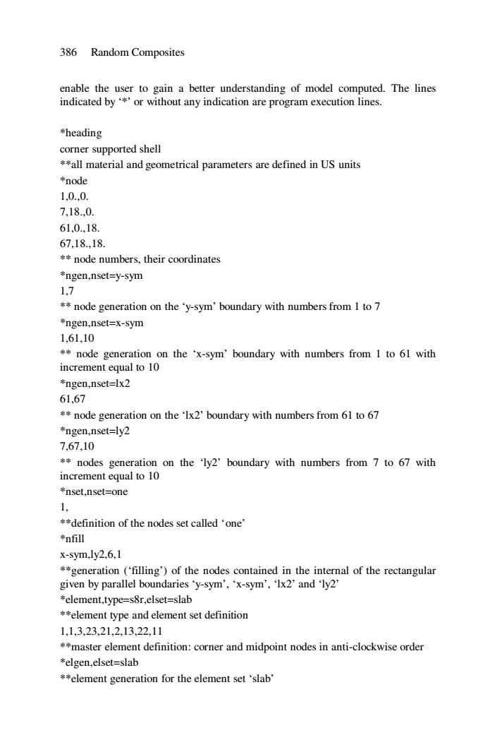
386 Random Composites enable the user to gain a better understanding of model computed. The lines indicated by ‘*’ or without any indication are program execution lines. *heading corner supported shell **all material and geometrical parameters are defined in US units *node 1,0.,0. 7,18.,0. 61,0.,18. 67,18.,18. ** node numbers, their coordinates *ngen,nset=y-sym 1,7 ** node generation on the ‘y-sym’ boundary with numbers from 1 to 7 *ngen,nset=x-sym 1,61,10 ** node generation on the ‘x-sym’ boundary with numbers from 1 to 61 with increment equal to 10 *ngen,nset=lx2 61,67 ** node generation on the ‘lx2’ boundary with numbers from 61 to 67 *ngen,nset=ly2 7,67,10 ** nodes generation on the ‘ly2’ boundary with numbers from 7 to 67 with increment equal to 10 *nset,nset=one 1, **definition of the nodes set called ‘one’ *nfill x-sym,ly2,6,1 **generation (‘filling’) of the nodes contained in the internal of the rectangular given by parallel boundaries ‘y-sym’, ‘x-sym’, ‘lx2’ and ‘ly2’ *element,type=s8r,elset=slab **element type and element set definition 1,1,3,23,21,2,13,22,11 **master element definition: corner and midpoint nodes in anti-clockwise order *elgen,elset=slab **element generation for the element set ‘slab’