
三、 实验过程 1.打开并显示SP0T数据和Landsat TM数据 从ENVI主菜单中,选择file→open image file.打开zhangan_.bldr_sp.img 和zhang_.bldr_tm.img文件。点击ok。选中zhangan_bldr_sp.img文件,点击 Load Band按钮,加载这幅影像到一个显示窗口中。再选中zhang bldr tm.img 文件。 点击display#1按钮,并从下拉式菜单中选择new display。点击Load Band按 钮,把TM的band3波段的影像加载到一个新的显示窗口中。 从主影像窗口菜单栏中,选择tools→Cursor Location/value。在主影像 窗口、滚动窗口和缩放窗口的TM影像上,移动鼠标光标。光标位置信息对话框 会显示影像的详细信息。 Cursor Location/Value ▣回X File Options Disp1(739,180)Scrn:R:137G:137B:137 Projection:UTM,Zone 13 North Map:475414.00E,4439689.00 N Meters LL:40?32.53“H,105?7'18.53W Data:50 图2.1 Cursor Location,/value显示窗▣ 2.开始进行影像配准 从ENVI主菜单栏中,选择Map→Registration→Select GCPs:Image to Image。在image to Image Registration对话框中,点击并选择display#l, 作为Base Image。.点击display#2作为Warp image。 Image to Image Registration X Select displays containing images: Base Image Warp Image Display #1 Display #1 Display #2 Display #2 Selected Item: Selected Item: Display #1 Display #2 OK Cancel 图2.2 image to Image Registration对话框 点击ok,启动自动配准程序。通过讲光标放置在两幅影像的相同地物点上
三、 实验过程 1. 打开并显示 SPOT 数据和 Landsat TM 数据 从ENVI主菜单中,选择file →open image file。打开zhangan_bldr_sp.img 和 zhang_bldr_tm.img 文件。点击 ok。选中 zhangan_bldr_sp.img 文件,点击 Load Band 按钮,加载这幅影像到一个显示窗口中。再选中 zhang_bldr_tm.img 文件。 点击 display#1 按钮,并从下拉式菜单中选择 new display。点击 Load Band 按 钮,把 TM 的 band3 波段的影像加载到一个新的显示窗口中。 从主影像窗口菜单栏中,选择 tools →Cursor Location/value。在主影像 窗口、滚动窗口和缩放窗口的 TM 影像上,移动鼠标光标。光标位置信息对话框 会显示影像的详细信息。 图 2.1 Cursor Location/value 显示窗口 2. 开始进行影像配准 从 ENVI 主菜单栏中,选择 Map →Registration →Select GCPs:Image to Image。在 image to Image Registration 对话框中,点击并选择 display#1, 作为 Base Image。点击 display#2 作为 Warp image。 图 2.2 image to Image Registration 对话框 点击 ok,启动自动配准程序。通过讲光标放置在两幅影像的相同地物点上
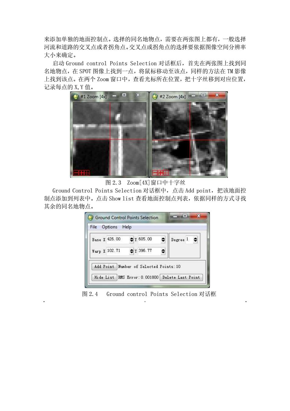
来添加单独的地面控制点。选择的同名地物点,需要在两张图上都有,一般选择 河流和道路的交叉点或者拐角点。交叉点或拐角点的选择要依据图像空间分辨率 大小来确定。 启动Ground control Points Selection对话框后,首先在两张图上找到同 名地物点,在SPOT图像上找到一点,将鼠标移动至该点,同样的方法在TM影像 上找到该点。在两个Z00m窗口中,查看光标所在位置,把十字丝移到对应位置, 记录每点的X,Y值。 ●1Zoom4- 日田 图2.3Zoom[4X]窗口中十字丝 Ground Control Points Selection对话框中,点击Add point,把该地面控 制点添加到列表中。点击Show list查看地面控制点列表,依据同样的方式寻找 其余的同名地物点。 Ground Control Points Selection File Options Help Base X 426.00 ÷Y605.00 Degree1÷ WrpX102.71 y396.77 Add Point Number of Selected Points:10 Hide List RMS Error:0.001800 Delete Last Point 图2.4 Ground control Points Selection对话框
来添加单独的地面控制点。选择的同名地物点,需要在两张图上都有,一般选择 河流和道路的交叉点或者拐角点。交叉点或拐角点的选择要依据图像空间分辨率 大小来确定。 启动 Ground control Points Selection 对话框后,首先在两张图上找到同 名地物点,在 SPOT 图像上找到一点,将鼠标移动至该点,同样的方法在 TM 影像 上找到该点。在两个 Zoom 窗口中,查看光标所在位置,把十字丝移到对应位置, 记录每点的 X,Y 值。 图 2.3 Zoom[4X]窗口中十字丝 Ground Control Points Selection 对话框中,点击 Add point,把该地面控 制点添加到列表中。点击 Show list 查看地面控制点列表,依据同样的方式寻找 其余的同名地物点。 图 2.4 Ground control Points Selection 对话框
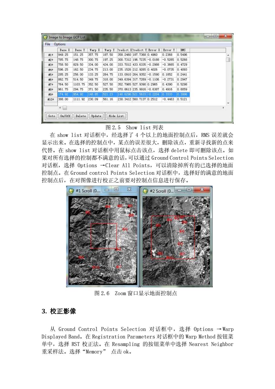
Image to Image GCP List 回X File Options Base X Base I Warp X Warp Y Predict XPredict I Error X Error Y RMS #1十 949.25151.25 357.75187.50 358.2460187.73680.4960 0.23680.5498 2+ 785.75 148.75 300.75197.25 300.7312196.7235-0.0188 -0.52850.5268 3+ 758.50829.50 334.00 434.00 333.7012433.6335-0.2988-0.3885 0.4729 #料+ 596.25182.50234.75213.00 235.1526212.92B50.4028 -0.07350.4093 5+285.25256.00133.25284.75 133.0910264.g352-0.15900.18520.2441 6+ 862.75514.50349.75318.00349.6394317.7269-0.1106-0.27310.2947 764.501103.75352.50527.50352.7965527.93900.29650.43900.5298 3+ 961.75294.75371.50235.50370.8613235.9916-0.63870.49160.8059 韵+ 174929549214885521.23148.62s85215583-0.22040.33330.398 #10+ 388.001111.92230.09561.16230.3412560.71370.2512-0.44630.5121 Goto On/Off Delete Update Hide List 图2.5Show1ist列表 在show list对话框中,经选择了4个以上的地面控制点后,RMS误差就会 显示出来。在选择的控制点中,某点的误差很大,删除该点,重新寻找新的点来 代替。在show list对话框中用鼠标点击该点,选择delete即可删除该点。如 果对所有选择的控制都不满意的话,可以通过Ground Control Points Selection 对话框,选择Options→Clear Al1 Points.,可以清除掉所有的已选择的地面 控制点。在Ground control Points Selection对话框中,选择好的满意的地面 控制点后,在对图像进行校正之前要对控制点信息进行保存。 #2 Scroll0.回X 图2.6Z0om窗口显示地面控制点 3.校正影像 从Ground Control Points Selection对话框中,选择Options→Warp Displayed Band。.在Registration Parameters对话框中的Warp Method按钮菜 单中,选择RST校正法。在Resampling的按钮菜单中选择Nearest Neighbor 重采样法。选择“Memory”点击ok
图 2.5 Show list 列表 在 show list 对话框中,经选择了 4 个以上的地面控制点后,RMS 误差就会 显示出来。在选择的控制点中,某点的误差很大,删除该点,重新寻找新的点来 代替。在 show list 对话框中用鼠标点击该点,选择 delete 即可删除该点。如 果对所有选择的控制都不满意的话,可以通过 Ground Control Points Selection 对话框,选择 Options →Clear All Points,可以清除掉所有的已选择的地面 控制点。在 Ground control Points Selection 对话框中,选择好的满意的地面 控制点后,在对图像进行校正之前要对控制点信息进行保存。 图 2.6 Zoom 窗口显示地面控制点 3. 校正影像 从 Ground Control Points Selection 对话框中,选择 Options →Warp Displayed Band。在 Registration Parameters 对话框中的 Warp Method 按钮菜 单中,选择 RST 校正法。在 Resampling 的按钮菜单中选择 Nearest Neighbor 重采样法。选择“Memory” 点击 ok

Registration Parameters 一Warp Parameters Method RST Resampling Nearest Neighbor Background 0 -Output Image Extent Upper Left X -36 Upper Left Y -552 Output Samples 2029 Output Lines 2593 9 Output Result to File Memory OK Queue Cancel 图2.7 Registration Parameters对话框 ●y#3 Scroll(0.09 一▣X 图2.8RST校正法的Nearest Neighbor重采样后的TM影像 使用RST校正法,选择Bilinear重采样法。方法与上面类似
图 2.7 Registration Parameters 对话框 图 2.8 RST 校正法的 Nearest Neighbor 重采样后的 TM 影像 使用 RST 校正法,选择 Bilinear 重采样法。方法与上面类似
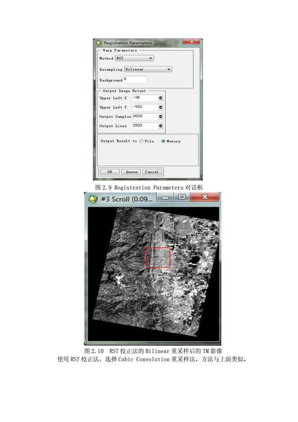
Registration Parameters Warp Parameters Method RST Resampling Bilinear Background 0 Output Image Extent Upper Left X -36 Upper Left Y -552 Output Samples 2029 Output Lines 2593 0 utput Result to○File ⊙)Memory OK Queue Cancel 图2.9 Registration Parameters对话框 #3 Scroll (0.09... 图2.l0RST校正法的Bilinear重采样后的TM影像 使用RST校正法,选择Cubic Convolution重采样法。方法与上面类似
图 2.9 Registration Parameters 对话框 图 2.10 RST 校正法的 Bilinear 重采样后的 TM 影像 使用 RST 校正法,选择 Cubic Convolution 重采样法。方法与上面类似