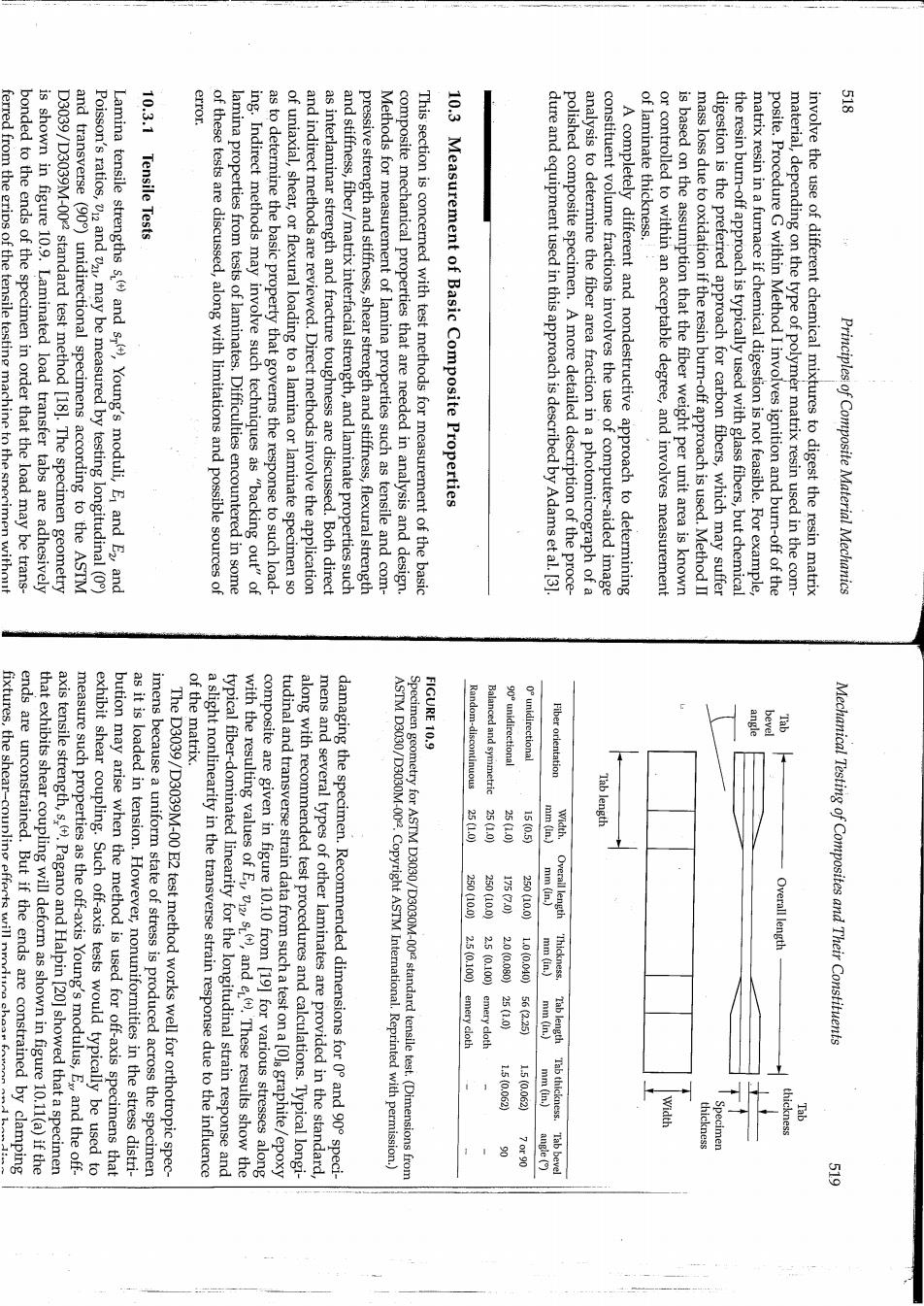
error. 贵 ferred from the grips of the tensile testing machine to the specimen without bonded to the ends of the specimen in order that the load may be trans- is shown in figure 10.9.Laminated load transfer tabs are adhesively D3039/D3039M-002 standard test method [18].The specimen geometry and transverse (90)unidirectional specimens according to the ASTM Poisson's ratios,v12 and vz may be measured by testing longitudinal (0) Lamina tensile strengths s.()and s),Young's moduli,E and E2,and 10.3.1 Tensile Tests of these tests are discussed,along with limitations and possible sources of lamina properties from tests of laminates.Difficulties encountered in some ing.Indirect methods may involve such techniques as "backing out"of as to determine the basic property that governs the response to such load- of uniaxial,shear,or flexural loading to a lamina or laminate specimen so and indirect methods are reviewed.Direct methods involve the application as interlaminar strength and fracture toughness are discussed.Both direct and stiffness,fiber/matrix interfacial strength,and laminate properties such pressive strength and stiffness,shear strength and stiffness,flexural strength Methods for measurement of lamina properties such as tensile and com- composite mechanical properties that are needed in analysis and design. This section is concerned with test methods for measurement of the basic 10.3 Measurement of Basic Composite Properties dure and equipment used in this approach is described by Adamset al.[3] polished composite specimen.A more detailed description of the proce- analysis to determine the fiber area fraction in a photomicrograph of a constituent volume fractions involves the use of computer-aided image A completely different and nondestructive approach to determining of laminate thickness. or controlled to within an acceptable degree,and involves measurement is based on the assumption that the fiber weight per unit area is known mass loss due to oxidation if the resin burn-off approach is used.Method II digestion is the preferred approach for carbon fibers,which may suffer the resin burn-off approach is typically used with glass fibers,but chemical matrix resin in a furnace if chemical digestion is not feasible.For example, posite.Procedure G within Method I involves ignition and burn-off of the material,depending on the type of polymer matrix resin used in the com- involve the use of different chemical mixtures to digest the resin matrix Principles of Composite Material Mechanics ends are unconstrained.But if the ends are constrained by clamping fixtures,the shear-coupling efferts will nrod of the matrix. FIGURE 10.9 Random-discontinuous 90 unidirectional unidirectional Fiber orientation that exhibits shear coupling will deform as shown in figure 10.11(a)if the axis tensile strength,s,().Pagano and Halpin [20]showed that a specimen measure such properties as the off-axis Young's modulus,Ex and the off- exhibit shear coupling.Such off-axis tests would typically be used to bution may arise when the method is used for off-axis specimens that as it is loaded in tension.However,nonuniformities in the stress distri- imens because a uniform state of stress is produced across the specimen The D3039/D3039M-00 E2 test method works well for orthotropic spec- a slight nonlinearity in the transverse strain response due to the influence typical fiber-dominated linearity for the longitudinal strain response and with the resulting values of E),and e().These results show the composite are given in figure 10.10 from [191 for various stresses along tudinal and transverse strain data from such a test on a [Ols graphite/epoxy along with recommended test procedures and calculations.Typical longi- mens and several types of other laminates are provided in the standard. damaging the specimen.Recommended dimensions for 0 and 90 speci- ASTM D3030/D3030M-002.Copyright ASTM International.Reprinted with permission.) Balanced and symmetric ecimen geometry for ASTM D3030/D3030M-00 standard tensile test.(Dimensions from Tab length 25100 25100 150.5 ) 250800 17500 Overall length mm (in.) Overall length 2.5(0.100)emery cloth 250100 20(0080025000 250000010(0.040056235 mm (in.) Thick Mechanical Testing of Composites and Their Constituents 9 emery cloth 15(0.0620 .5(00622 Tab length Tab thickness 工广 留
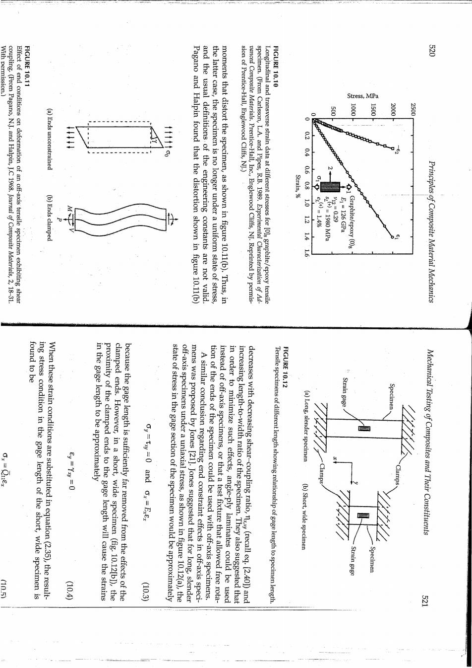
With permission. FIGURE 10.11 FIGURE 10.10 coupling.(From Pagano,N.J.and Halpin,J.C 1968.Journal of Composite Materials,2,18-31. Effect of end conditions on deformation of an off-axis tensile specimen exhibiting shear Stress,MPa 500 2500 (a)Ends unconstrained Pagano and Halpin found that the distortion shown in figure 10.11(b) and the usual definitions.of the engineering constants are not valid the latter case,the specimen is no longer under a uniform state of stress, moments that distort the specimen,as shown in figure 10.11(b).Thus,in sion of Prentice-Hall,Englewood Cliffs,N].) vanced Composite Materials.Prentice-Hall,Inc.Englewood Cliffs,N.Reprinted by permis- specimen.(From Carlsson,L.A.and Pipes,R.B.1989.Experimental Characterization of Ad- Longitudinal and transverse strain data at different stresses for [O]graphite/epoxy tensile 02 Strain, 0.60.8 1 (b)Ends clamped -0.29 1214 1V-14 E1=126 GPa Graphite/epoxy (0)8 Principles of Composite Material Mechanics When these strain conditions are substituted in equation(2.35),the result- ing stress condition in the gage length of the short,wide specimen is found to be in the gage length to be approximately FIGURE 10.12 611810 clamped ends.However,in a short,wide specimen (fig.10.12[b1),the proximity of the clamped ends to the gage length will cause the strains because the gage length is sufficiently far removed from the effects of the oy=txy=0 and ox=Exex off-axis specimens under a uniaxial stress,as shown in figure 10.12(a),the state of stress in the gage section of the specimen would be approximately mens was proposed by Jones [211.Jones suggested that for long,slender tion of the ends of the specimen could be used with off-axis specimens. A similar conclusion regarding end constraint effects in off-axis speci- instead of off-axis specimens,or that a test fixture that allowed free rota- in order to minimize such effects,angle-ply laminates could be used decreases with decreasing shear-coupling ratio,(recalleq.[2.401)and increasing length-to-width ratio of the specimen.They also suggested that Tensile specimens of different length showing relationship of gage length to specimen length Strain gage (a)Long,slender specimen Clamps (b)Short,wide specimen Mechanical Testing of Composites and Their Constituents Strain gage Specin 4o0 (10.3)
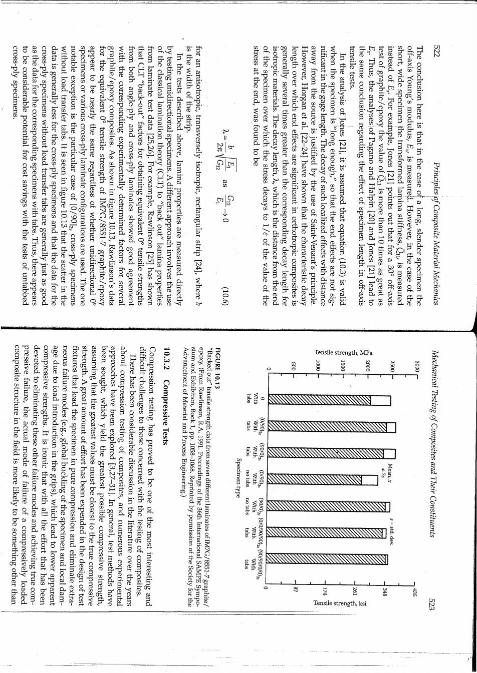
3 cross-ply specimens. tensile tests. to be considerable potential for cost savings with the tests of untabbed as the data for the corresponding specimens with tabs.Thus,there appears cross-ply specimens without load transfer tabs are generally just as good data is generally less for the cross-ply specimens and that the data for the without load transfer tabs.It is seen in figure 10.13 that the scatter in the notable exception is the particular case of [0/9012s cross-ply specimens specimens or various cross-ply laminate configurations are used.The one appear to be nearly the same regardless of whether unidirectional 0 for the equivalent 0 tensile strength of IM7G/8551-7 graphite/epoxy graphite/epoxy composites.As shown in figure 10.13,Rawlinson's data with the corresponding experimentally determined factors for several from both angle-ply and cross-ply laminates showed good agreement that CLT "back-out"factors for obtaining equivalent 0o tensile strengths from laminate test data [25,26].For example,Rawlinson [25]has shown of the classical lamination theory (CLT)to "back out"lamina properties by testing unidirectional specimens.A different approach involves the use In the tests described above,lamina properties are measured directly is the width of the strip. for an anisotropic,transversely isotropic,rectangular strip [24],where b stress at the end,was found to be as 出10 of the specimen over which the stress decays to 1/e of the value of the isotropic materials.The decay length,A,which is the distance from the end generally several times greater than the corresponding decay length for length over which end effects are significant in orthotropic composites is However,Horgan et al.[22-24]have shown that the characteristic decay away from the source is justified by the use of Saint-Venant's principle. nificant in the gage length.The decay of such localized effects with distance when the specimen is"long enough,"so that the end effects are not sig- In the analysis of Jones [21],it is assumed that equation(10.3)is valid the same conclusion regarding the effect of specimen length in off-axis E.Thus,the analyses of Pagano and Halpin [20]and Jones [21]lead to test of graphite/epoxy the value of Qu is more than 10 times as great as instead of E For example,Jones [21]points out that for a 30 off-axis short,wide specimen the transformed lamina stiffness,Qu is measured off-axis Young's modulus,E is measured.However,in the case of the The conclusion here is that in the case of a long,slender specimen the Principles of Composite Material Mechanics 10.6 10.3.2 Tensile strength,MPa FIGURE 10.13 50( 1000 3000 composite structure in the field is more likely to be something other than pressive failure,the actual mode of failure of a compressively loaded devoted to eliminating these other failure modes and achieving true com- compressive strengths.It is ironic that with all the effort that has been age due to load introduction in the grips),which lead to lower apparent neous failure modes(e.g global buckling of the specimen and local dam- fixtures that load the specimen in pure compression and eliminate extra- strength.A great amount of effort has been expended in the design of test assuming that the greatest values must be closest to the true compressive been sought,which yield the greatest possible compressive strength approaches have been explored [3,27-31].In general,test methods have about compression testing of composites,and numerous experimental difficult challenges to those concerned with the testing of composites. There has been considerable discussion in the literature over the years Compression testing has proved to be one of the most interesting and Compressive Tests Advancement of Material and Process Engineering.) epoxy.(From Rawlinson,R.A.1991.Proceedings of the 36th International SAMPE Sympo- sium and Exhibition,Book 1,pp.1058-1068.Reprinted by permission of the Society for the "Backed out"tensile strength data from seven different laminates of IM7G/8551-7graphite/ with Specimen type no tabs no tabs Mechanical Testing of Composites and Their Constituents Tensile strength,ksi
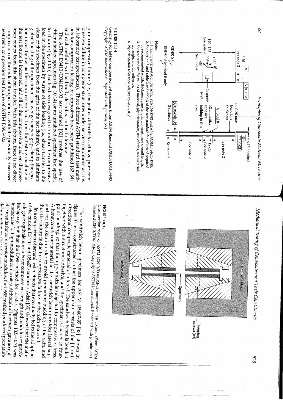
FIGURE 10.14 图 Notes: neat resin compression test fixture of ASTM D695-02a. See note 2 140-155 compression on the ends of the specimen as with the previously discussed imen comes from this shear transfer.With this fixture,there is no direct the test fixture is increased,and all of the compressive load on the spec- imen ever tighter as the compressive load from the testing machine on global buckling of the specimen.The wedge-shaped grips clamp the spec- sides of the specimen from the grips of the test fixture),and to eliminate load in the specimen by virtue of side loading (i.e.,shear transfer to the test fixture(fig.10.15)that has been designed to introduce the compressive either a tabbed specimen(fig.10.14)or an untabbed specimen in a special SIDES 0.8 The ASTM D3410/D3410M-03 test method [32]involves the use of and each method will be briefly described in the following. ods for compression testing of composites have been published [32-341 in laboratory test specimens).Three different ASTM standard test meth- pressive failure in composite structures under service conditions as it is pure compressive failure(i.e.,it is just as difficult to achieve pure com- Copyright ASTM International.Reprinted with permission.) Geometry for tabbed compression test specimen.(From ASTM Standard D3410/D3410M-03. 4.Ply orientation tolerance relative to-A-=0.5 tab angle,and tab adhesive. 3.See test standard for values of material,ply orientation,use of tabs,tab material, 2.See section 8 and table 2 and table3 of the test standard for values of required 1.Drawing interpretation per ANSI Y14.5M-1982 and ANSI/ASME 846.1-1985 ENDS 0.8 Method B only See note4 See note 2- 6.25 or recommended width,thickness,gage length,tab length and overall length. 图 2x strain 7808A 2surtaces G05888 area buildup in this adhesive 4X minimize thickness bond line X025max -See note 2 图 See note 2 See note 2 12-25 See note 2 -4x 15 nominal Principles of Composite Material Mechanics able results for compression modulus,the D695 method produced premature delamination or ch FIGURE 10.15 inadequate for high-modulus composites.Although all methods gave accept- ite/epoxy,but that the D695 method for plastics (Figures 10.5-10.7)was ods gave equivalent results for compressive strength and modulus of graph- of the current D3410 and D5467 standards,Adsit [35]showed that the meth- thus the failure is due to compressive failure of the skin material. In a comparison of several test methods that eventually led to the adoption port for the skin in order to avoid premature buckling of the skin,and point bending,so that the upper skin is subjected to compressive stress. A honeycomb core material in the sandwich beam provides lateral sup- together with a structural adhesive,and the specimen is loaded in four- directional composite material of interest.The sandwich beam is bonded figure 10.16 is constructed so that the upper skin consists of the [0]uni- The sandwich beam specimen for ASTM D5467-97 [33]shown in Standard D3410/D3410M-03.Copyright ASTM International.Reprinted with permission.) Cross-section view of ASTM D3410/D3410M-03 compression test fixture.(From ASTM housing bloc Mechanical Testing of Composites and Their Constituents crews (X4 Clamping 图

mission.) FIGURE 10.16 物 (1.5 in)he 40 mm. plane compressive strength after delamination due to transverse impact The problem of local buckling and the corresponding reduction of in- "backed out"of [0/90]cross-ply laminate compression test data [37]. rial.Compressive properties of the [o]unidirectional lamina can also be consisting of the neat resin matrix material instead of a honeycomb mate- specimen [36]is smaller than that used in ASTM D5467 and has a core ulus and strength have been reported in the literature.The minisandwich Anumber of alternative methods for measurement of compressive mod- shear load on the sides of the specimen can be adjusted for best results. and the ratio of direct compressive load on the ends of the specimen to the relatively simple and compact,no end tabs are required on the specimens, has several advantages over the other two methods.The CLC fixture is length of the specimen.Adams et al.[3]have suggested that the CLC method transfer through side loading to produce pure compression within the gage of direct compression on the ends of an untabbed specimen and shear compression(CLC)test.The CLC fixture (fig.10.17)involves a combination testing of composites is D6641/D6641M-01e1 [34],the combined loading The third version of the ASTM standard test methods for compression ASTM Standard D5467/D5467M-97.Copyright ASTM International.Reprinted 'with per ASTM D5467/D5467M-97 sandwich beam specimen for face sheet compression.(From Loading cylinder Core material Strain gage 1 22.0im 550mm 100mm Opposite skin 20mm0350-712000035mm +取 Test skin 200 mm Strain gage 2 (1.0 in)w 25 mm Principles of Composite Material Mechanics of statically induced or impact-induced damage. FIGURE 10.17 compressive residual strength of composite plates with various amounts 7137/D7137M-05e1.The result of this sequence of tests is data on the the specimens are subjected to in-plane compression according to ASTM D6264 or drop-weight impact damage according to ASTM D7136 and then subjected to either quasistatic indentation damage according to ASTM and the test fixture is shown in figure 10.18.First,the test specimens are strength properties of damaged polymer matrix composite plates [401 Standard D7137/D7137M-05e1 on measurement of compressive residual Still more recent work on CAI has led to the development of ASTM after impact(CAD test. about this failure mode has led to the development of the compression have been discussed in chapter 7(fig.7.39)and in chapter 9.Concern D6641M-01.Copyright ASTM International.Reprinted with permission.) Test fixture for ASTM D6641/D6641M-01 CLC test method.(From ASTM Standard D6641/ bearings screws Clamping and linear Alignment rods Specimen 48 mm (1.9 in)- Mechanical Testing of Composites and Their Constituents extensometer Kecess for (gage length) 12.7 mm (0.5 in) 64mn2.5im) 53 mm (2.1 in) 3