Optical Spectroscopy and Instrumentation (Chapter 7) (IR,visible and UV) pathlength b concentration c Transmittance T=I 10 Percent Transmittance %T= 1×100% Io Absorbance A=-logT =-o80 I 二1og1 Examples: T=1.00(100%T),A=0.00 T=0.10(10%T),A=1.00 T=0.001(0.1%T),A=3.00 CEM 333 page 3.1
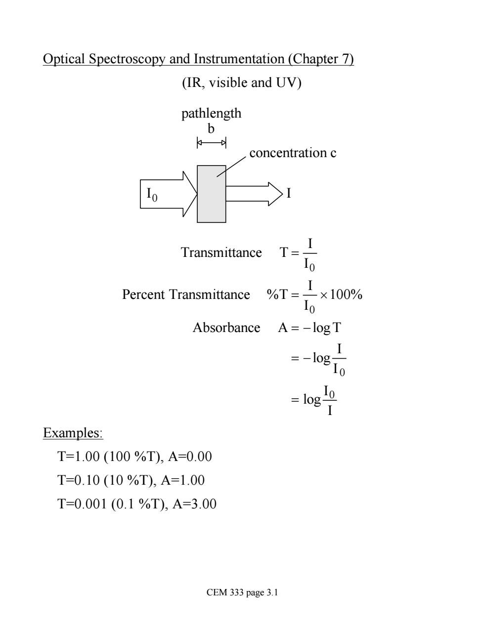
Optical Spectroscopy and Instrumentation (Chapter 7) (IR, visible and UV) I0 I pathlength b concentration c Transmittance T = I I0 Percent Transmittance %T = I I0 ´100% Absorbance A = -logT = -log I I 0 = log I0 I Examples: T=1.00 (100 %T), A=0.00 T=0.10 (10 %T), A=1.00 T=0.001 (0.1 %T), A=3.00 CEM 333 page 3.1
Beer's Law: Basis for absorbance spectrophotometry A ccc and A ocb S0Acb·c A=ab·c proportionality constant absorptivity units of L/g.cm If units of concentration are M(mol/L)then use molar absorptivity s A=8.b.c units of L/mol.cm Phenomena used for optical measurements, (1)Absorption(2)Emission (3)Luminescence (Fluorescence, Phosphorescence,Chemiluminescence(4)Scattering In all cases,response is proportional to concentration of analyte CEM 333 page 3.2
Beer's Law: Basis for absorbance spectrophotometry A µ c and A µ b so A µ b ×c A = a × b× c proportionality constant absorptivity - units of L/g·cm If units of concentration are M (mol/L) then use molar absorptivity e A = e× b ×c units of L/mol·cm Phenomena used for optical measurements, (1) Absorption (2) Emission (3) Luminescence (Fluorescence, Phosphorescence, Chemiluminescence (4)Scattering In all cases, response is proportional to concentration of analyte CEM 333 page 3.2
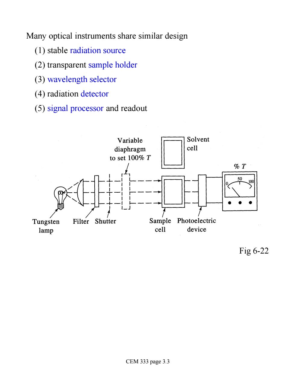
Many optical instruments share similar design (1)stable radiation source (2)transparent sample holder (3)wavelength selector (4)radiation detector (5)signal processor and readout Variable Solvent diaphragm cell to set 100%T %T ● Tungsten Filter Shutter Sample Photoelectric lamp cell device Fig 6-22 CEM 333 page 3.3
Many optical instruments share similar design (1) stable radiation source (2) transparent sample holder (3) wavelength selector (4) radiation detector (5) signal processor and readout Fig 6-22 CEM 333 page 3.3
Radiation Sources (Fig.7-3) Wavelength.nm 100 200 400 IR (a)Sources Hr Da lamp Continuur yer亿0+Y0) Nichrome wire (Ni+Cr) Globar (sic Photographic plate Photomultiplier tube Phototube Photocell Silicon diode Charge-transfer detecto Thern couple (voltage)or bolometer (resi Golay pneumatic cell CEM 333 page 3.4
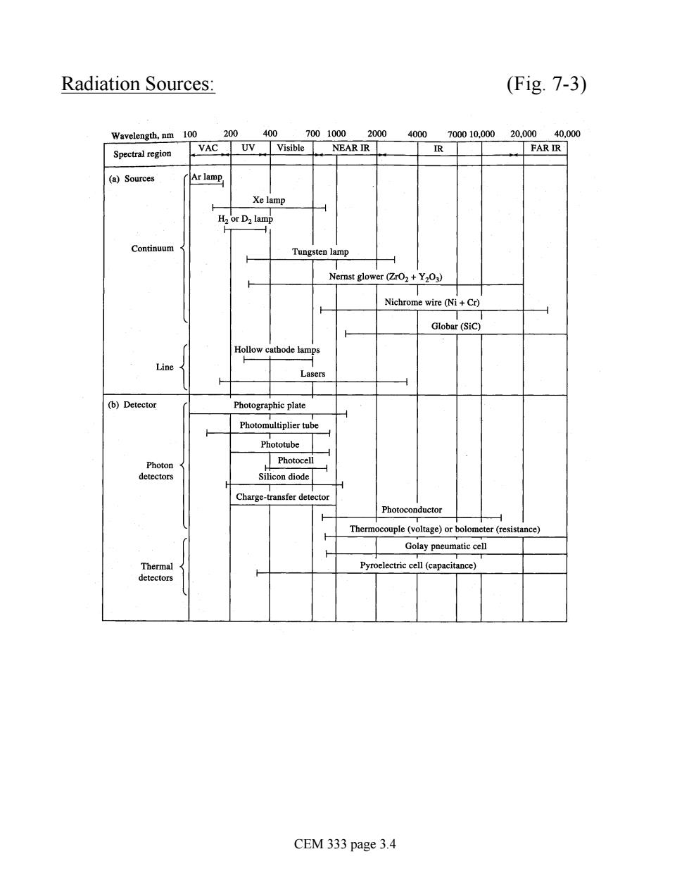
Radiation Sources: (Fig. 7-3) CEM 333 page 3.4
Continuum sources produce broad range of 's(often blackbody) Heated solid (Globar,nichrome wire)(1-40 um) Tungsten lamp (300-3000 nm) Quartz Tungsten Halogen (QTH)lamp(200-3000 nm) high temperature(3500 K) Evaporation W(s)->W(g) W(g)+I2(g)→W12(g) Redeposition WI2(g)+W(s)>W(s)+I2(g) D2 lamp or Hg/Xe arc-lamp -(160-400 nm) electronic excitation D2+Eelectrical→D2*-→D(KE1)+D(KE2)+hv KE1+KE2+hv=Eelectrical-BDE bond dissociation energy CEM 333 page 3.5
Continuum sources produce broad range of l's (often blackbody) Heated solid (Globar, nichrome wire) (1-40 mm) Tungsten lamp (300-3000 nm) Quartz Tungsten Halogen (QTH) lamp (200-3000 nm) high temperature (3500 K) Evaporation W(s) ® W(g) W(g) + I2 (g) ® WI2 (g) Redeposition WI2 (g)+ W(s) ® W(s) + I2 (g) D2 lamp or Hg/Xe arc-lamp - (160-400 nm) electronic excitation D2 + Eelectrical ® D2 * ® D(KE1 ) + D(KE2 ) + hn KE1 + KE2 + hn = Eelectrical - BDE bond dissociation energy CEM 333 page 3.5