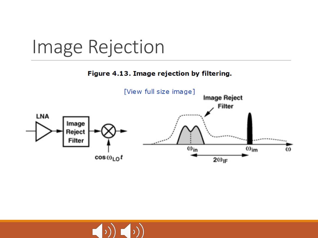
Image Rejection Figure 4.13.Image rejection by filtering. [View full size image] Image Reject Filter LNA Image Reject Filter Oim cosOLot 201F ))
Image Rejection
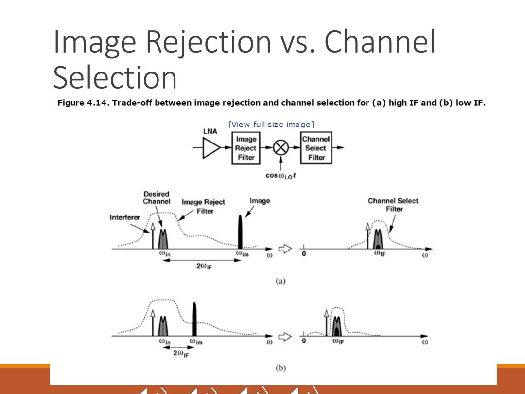
Image Rejection vs.Channe Selection Figure 4.14.Trade-off between image rejection and channel selection for (a)high IF and(b)low IF. [View full size image] LNA Image Channel Reject Select Filter Filter cos@Lot Desired Channel Image Reject Image Channel Select Filter Filter Interferer 0 20F (a) 00 (im ODIF 0 201E (b)
Image Rejection vs. Channel Selection
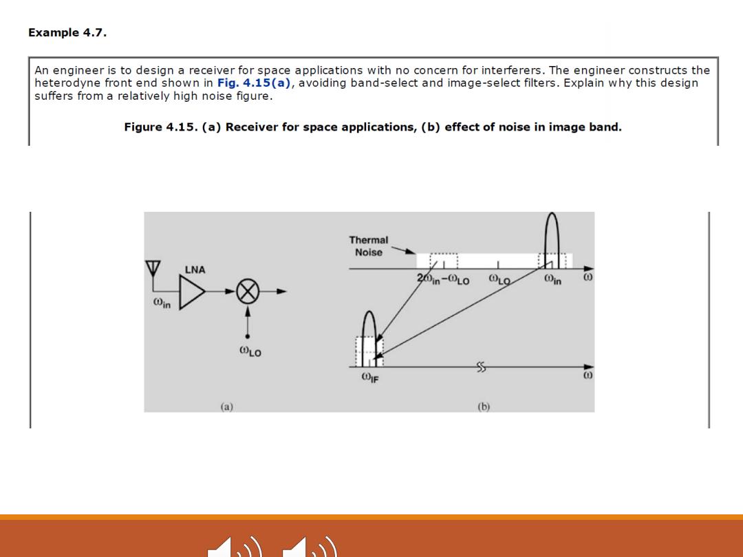
Example 4.7. An engineer is to design a receiver for space applications with no concern for interferers.The engineer constructs the heterodyne front end shown in Fig.4.15(a),avoiding band-select and image-select filters.Explain why this design suffers from a relatively high noise figure. Figure 4.15.(a)Receiver for space applications,(b)effect of noise in image band. Thermal Noise LNA 20in-(LO 0L0 ODin 0 ⊙n ①L0 (gF ① ( (b)
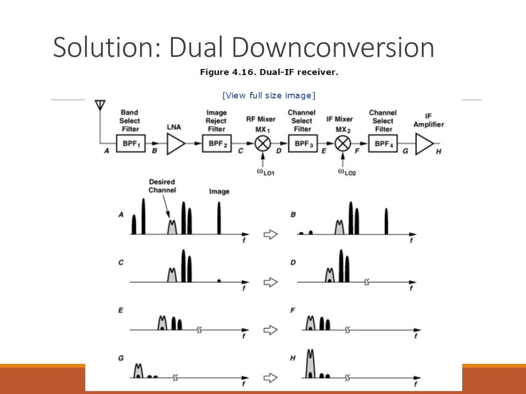
Solution:Dual Downconversion Figure 4.16.Dual-IF receiver. [View full size image] Band Image Channel Channel IF Select Reject RF Mixer Select IF Mixer Select Filter LNA Filter Amplifier MX1 Filter MX2 Filter BPF1 BPF2 BPF3 BPF4 0L01 @L02 Desired Channel Image
Solution: Dual Downconversion
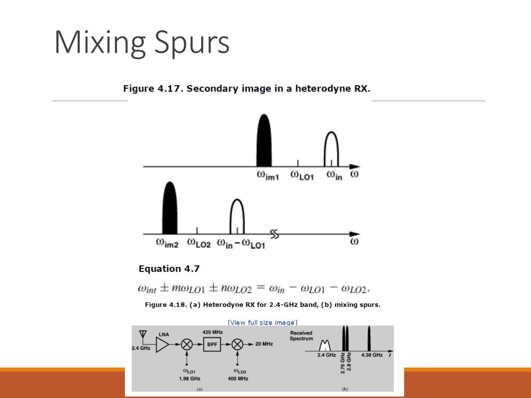
Mixing Spurs Figure 4.17.Secondary image in a heterodyne RX. 0m10L010in 0im20L0201n-0L01 o Equation 4.7 0imr士m1wL01士1wL02=①im-L01-0L02. Figure 4.18.(a)Heterodyne RX for 2.4-GHz band,(b)mixing spurs. [View full size image] LNA 420MH2 Recelved Spectrum 20 MHz M 2.4 GHz BPF Gt周 4.38GH7 0L01 0L02 1.98 GHz 400 MHz (a) b
Mixing Spurs