Chapter8 Seismic Design of Steel Structures of Buildings &.a86sinofs6oltlrs8foostoryfacto 8.1 Behavior of a steel structures 8.1 Failure Modes Lessons from earthquakes 8.1 Failure Modes w6m
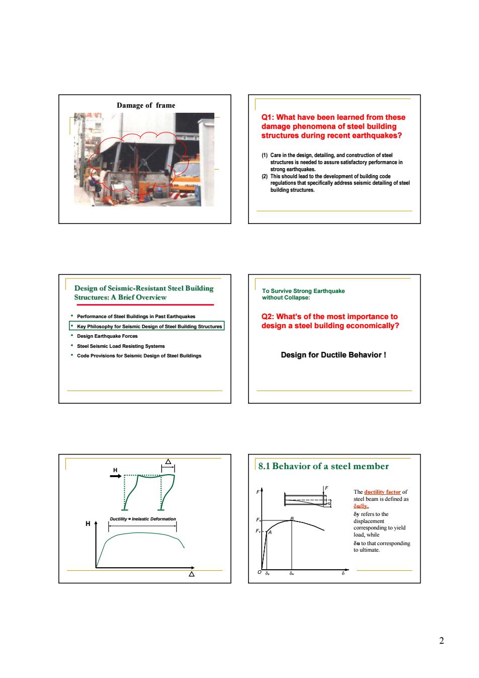
1 Chapter 8 Seismic Design of Steel Structures of Buildings 8.1 Behavior of a steel structures 8.2 Design of steel frames for middle and high rise buildings 8.2.1 Structural systems of middle and high rise buildings 8.2.2 Requirement for arrangement of steel structural systems 8.2.3 Calculation of earthquake action 8.2.4 Seismic check for member and section capacity 8.2.5 Detailing requirements for seismic design of members 8.2.6 Seismic check and detailing requirements 8.3 Design of steel structures of one storey factories 8.3.1 Requirements of structural system 8.3.2 Calculation of earthquake action 8.3.3 Seismic check for members and detailing requirement n Lessons from earthquakes n The damage or failure phenomena caused by earthquake can be classified as the following aspects: members, joints, whole systems, and non structural components. 8.1 Behavior of a steel structures 8.1 Failure Modes 8.1 Failure Modes Damage of joints
Damage of frame Q1:What have been learned from these To Svtong Earthquako ings in Past Earthquako tool Solsmi oad Ro Design for Ductile Behavior 8.1 Behavior of a steel member ers to止 H
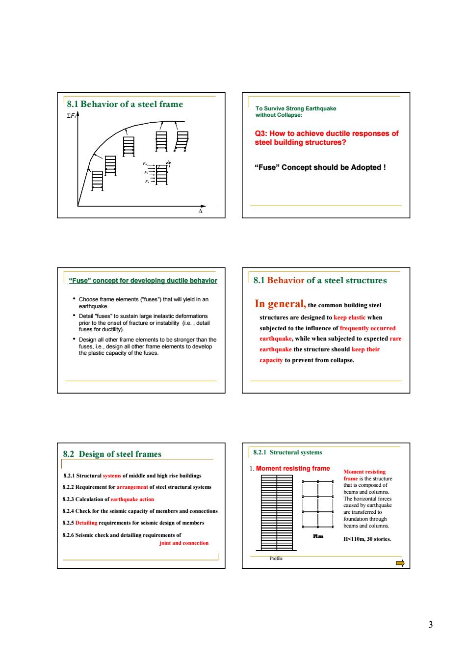
2 Damage of frame Q1: What have been learned from these damage phenomena of steel building structures during recent earthquakes? (1) Care in the design, detailing, and construction of steel structures is needed to assure satisfactory performance in strong earthquakes. (2) This should lead to the development of building code regulations that specifically address seismic detailing of steel building structures. • Performance of Steel Buildings in Past Earthquakes • Key Philosophy for Seismic Design of Steel Building Structures • Design Earthquake Forces • Steel Seismic Load Resisting Systems • Code Provisions for Seismic Design of Steel Buildings Design of Seismic-Resistant Steel Building Structures: A Brief Overview To Survive Strong Earthquake without Collapse: Design for Ductile Behavior ! Q2: What’s of the most importance to design a steel building economically? H H Ductility = Inelastic Deformation O dy du F y F u F A B F d d The ductility factor of steel beam is defined as du/dy, dy refers to the displacement corresponding to yield load, while du to that corresponding to ultimate. 8.1 Behavior of a steel member
8.1 Behavior of a steel frame 目 03Hblngtieecgerespons8sof "Fuse"Concept should be Adopted! "Fuse"concept for developing ductile behavior 8.1 Behavior of a steel structures Detail 'fus d to kee capacity to prevent from collapse. 8.2 Design of steel frames 8.2.1 Structural systems 8.2.2 Requirement for arrangement of steel structural system 8.23 Calculation of earthquake action 8.2.4 Cheek for the seismic capacity of members and co e te H<110m.30 stories 3
3 Fi F 1 D F n SFi D 8.1 Behavior of a steel frame To Survive Strong Earthquake without Collapse: “Fuse” Concept should be Adopted ! Q3: How to achieve ductile responses of steel building structures? “Fuse” concept for developing ductile behavior • Choose frame elements ("fuses") that will yield in an earthquake. • Detail "fuses" to sustain large inelastic deformations prior to the onset of fracture or instability (i.e. , detail fuses for ductility). • Design all other frame elements to be stronger than the fuses, i.e., design all other frame elements to develop the plastic capacity of the fuses. In general, the common building steel structures are designed to keep elastic when subjected to the influence of frequently occurred earthquake, while when subjected to expected rare earthquake the structure should keep their capacity to prevent from collapse. 8.1 Behavior of a steel structures 8.2 Design of steel frames 8.2.1 Structural systems of middle and high rise buildings 8.2.2 Requirement for arrangement of steel structural systems 8.2.3 Calculation of earthquake action 8.2.4 Check for the seismic capacity of members and connections 8.2.5 Detailing requirements for seismic design of members 8.2.6 Seismic check and detailing requirements of joint and connection Profile Plan 1. Moment resisting frame Moment resisting frame is the structure that is composed of beams and columns. The horizontal forces caused by earthquake are transferred to foundation through beams and columns. H<110m, 30 stories. 8.2.1 Structural systems
Braced frame structure and Frame with s oirt.are theoueh the same t Tube structures at both e ds or one en or a shor s20 .Structural systems of middle and high rise buildin on for building height 五 of the
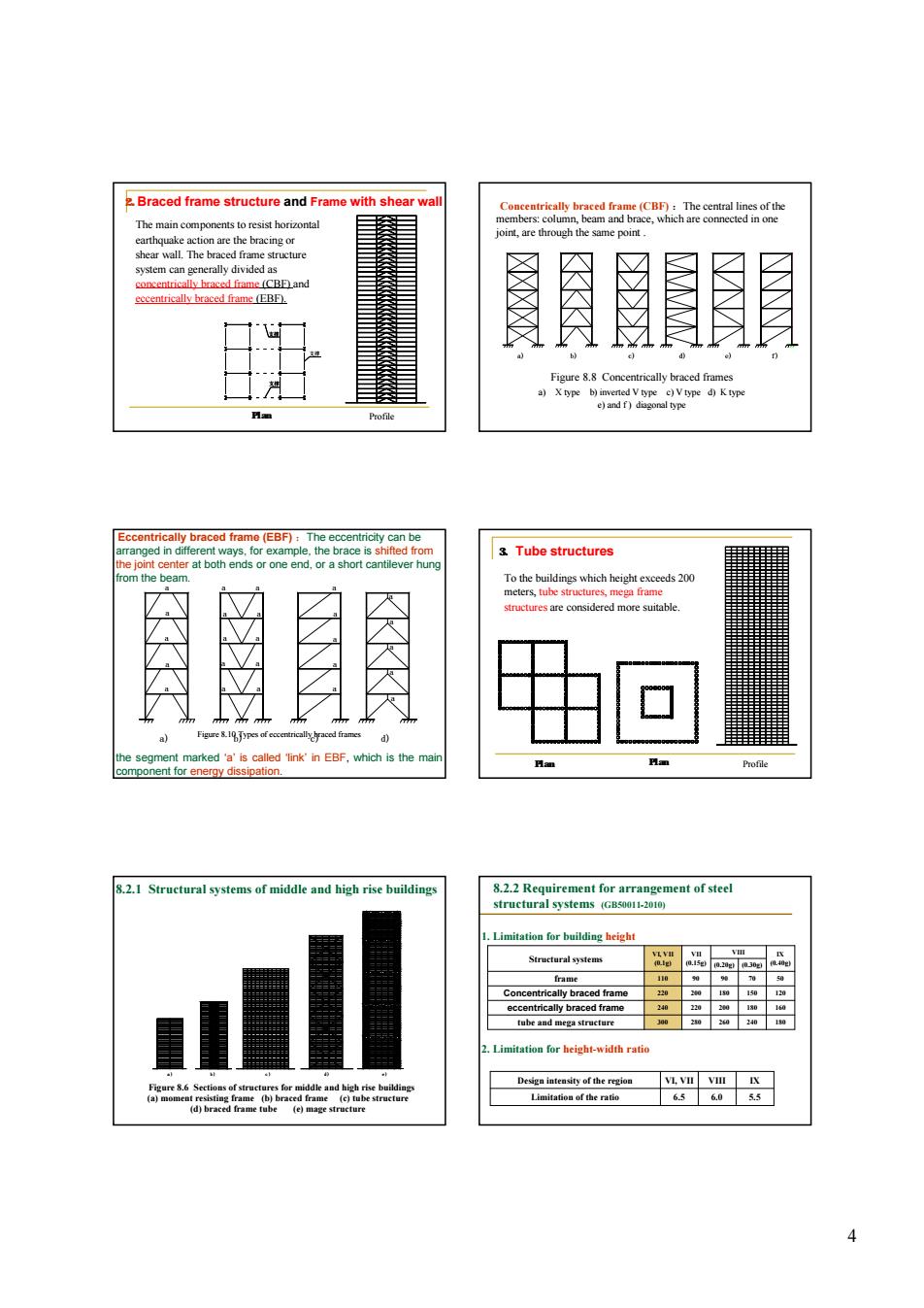
4 2.Braced frame structure and Frame with shear wall 支撑 支撑 支撑 The main components to resist horizontal earthquake action are the bracing or shear wall. The braced frame structure system can generally divided as concentrically braced frame (CBF) and eccentrically braced frame (EBF). Plan Profile Concentrically braced frame (CBF) :The central lines of the members: column, beam and brace, which are connected in one joint, are through the same point . Figure 8.8 Concentrically braced frames a) X type b) inverted V type c) V type d) K type e) and f ) diagonal type a) b) c) d) e) f) Eccentrically braced frame (EBF) :The eccentricity can be arranged in different ways, for example, the brace is shifted from the joint center at both ends or one end, or a short cantilever hung from the beam. a) a a a a a a a b) a a a a a a a a c) a a a a a d) a a a a a the segment marked ‘a’ is called ‘link’ in EBF, which is the main component for energy dissipation. Figure 8.10 Types of eccentrically braced frames 3. Tube structures To the buildings which height exceeds 200 meters, tube structures, mega frame structures are considered more suitable. Plan Plan Profile Figure 8.6 Sections of structures for middle and high rise buildings (a) moment resisting frame (b) braced frame (c) tube structure (d) braced frame tube (e) mage structure 8.2.1 Structural systems of middle and high rise buildings a ) b ) c ) d ) e ) 1. Limitation for building height 2. Limitation for height-width ratio 8.2.2 Requirement for arrangement of steel structural systems (GB50011-2010) tube and mega structure 300 280 180 Concentrically braced frame 220 200 120 frame 110 90 50 IX (0.40g) VII (0.15g) VI, VII (0.1g) Structural systems eccentrically braced frame 240 220 160 VIII 90 180 200 260 (0.20g) (0.30g) 70 150 180 240 Limitation of the ratio 6.5 6.0 5.5 Design intensity of the region VI, VII VIII IX
2agrmgmcaoa 3.Seismic Grading 袋 ≤50 4th 3rd 2nd 5.Laveut ef strustural svstem 504h 3d 2nd 1st ldeal failure mode 6.Resistant lines 2)In CBF st )hekaeteee 5.Enough rigid floor system 8.2.3 Computation of earthquake action e slab cast-in-pl 密 (3)Calculale the earthquake action.Three methods can be used (4)Seismic checkine for the members.comnecters.and bases. (5)Displacement checking (6)Details design
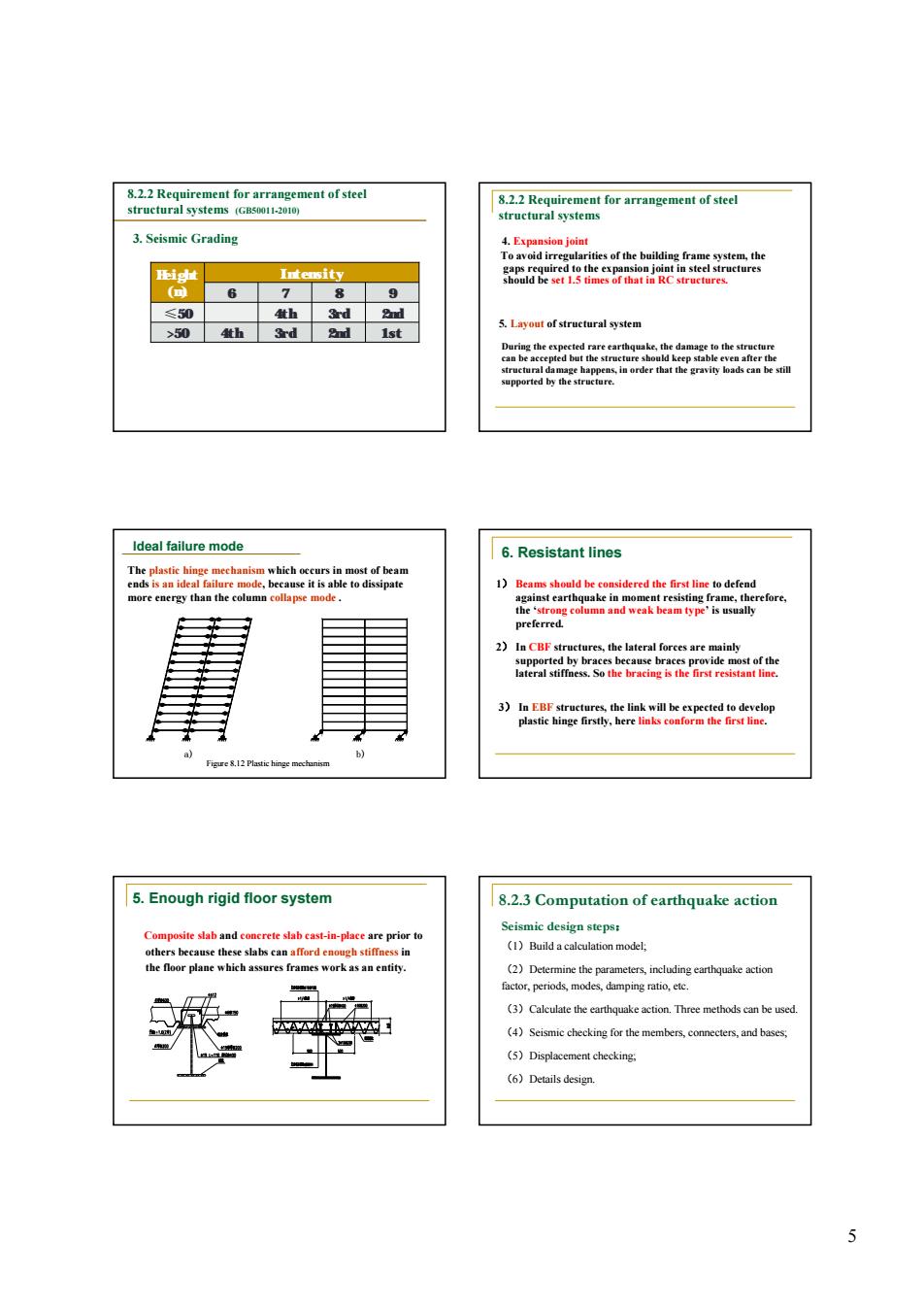
5 3. Seismic Grading 8.2.2 Requirement for arrangement of steel structural systems (GB50011-2010) Height (m) Intensity 6 7 8 9 ≤50 4th 3rd 2nd >50 4th 3rd 2nd 1st 4. Expansion joint To avoid irregularities of the building frame system, the gaps required to the expansion joint in steel structures should be set 1.5 times of that in RC structures. 5. Layout of structural system During the expected rare earthquake, the damage to the structure can be accepted but the structure should keep stable even after the structural damage happens, in order that the gravity loads can be still supported by the structure. 8.2.2 Requirement for arrangement of steel structural systems a) b) The plastic hinge mechanism which occurs in most of beam ends is an ideal failure mode, because it is able to dissipate more energy than the column collapse mode . Figure 8.12 Plastic hinge mechanism Ideal failure mode 2) In CBF structures, the lateral forces are mainly supported by braces because braces provide most of the lateral stiffness. So the bracing is the first resistant line. 3) In EBF structures, the link will be expected to develop plastic hinge firstly, here links conform the first line. 1) Beams should be considered the first line to defend against earthquake in moment resisting frame, therefore, the ‘strong column and weak beam type’ is usually preferred. 6. Resistant lines 5. Enough rigid floor system Composite slab and concrete slab cast-in-place are prior to others because these slabs can afford enough stiffness in the floor plane which assures frames work as an entity. (1)Build a calculation model; (2)Determine the parameters, including earthquake action factor, periods, modes, damping ratio, etc. (3)Calculate the earthquake action. Three methods can be used. (4)Seismic checking for the members, connecters, and bases; (5)Displacement checking; (6)Details design. 8.2.3 Computation of earthquake action Seismic design steps: