Seismic Steel Design 12/9/2012 Chapter 8 SEISMIC STEEL DESIGN IN CANADA and the USA .Earthquake Effects on Structuros Importance of Ductility .Design Earthquake Forces Load Resisting ystem Seismic Provision 。Concluding romarks @.ubc.ca Structural Steel in Build ◆F=ma 5nmamerorcea 77 by Dr.Carlos E.Ventura,UBC 1
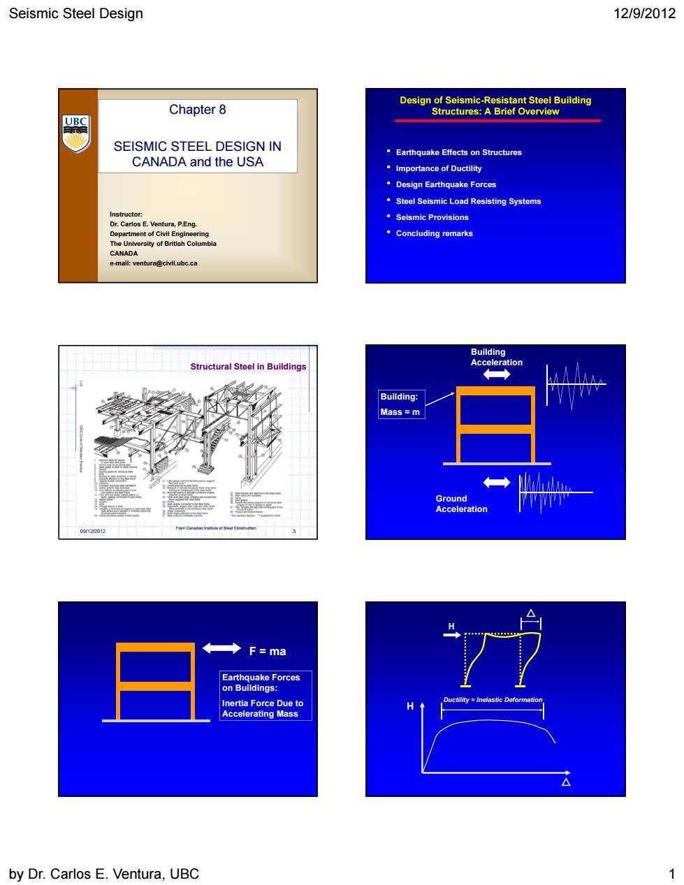
Seismic Steel Design 12/9/2012 by Dr. Carlos E. Ventura, UBC 1 Instructor: Dr. Carlos E. Ventura, P.Eng. Department of Civil Engineering The University of British Columbia CANADA e-mail: ventura@civil.ubc.ca Chapter 8 SEISMIC STEEL DESIGN IN CANADA and the USA Design of Seismic-Resistant Steel Building Structures: A Brief Overview • Earthquake Effects on Structures • Importance of Ductility • Design Earthquake Forces • Steel Seismic Load Resisting Systems • Seismic Provisions • Concluding remarks 09/12/2012 3 Structural Steel in Buildings From Canadian Institute of Steel Construction Ground Acceleration Building: Mass = m Building Acceleration F = ma Earthquake Forces on Buildings: Inertia Force Due to Accelerating Mass H H Ductility = Inelastic Deformation
Seismic Steel Design 12/9/2012 Nonductil Falure Modes:Fracture or Instabi Ductity Factor Design EQ Loads-Total Lateral Forc Developing Ductile Behavior: V=CW agen aw Basic Concept Design Earthquake Loads NBCC 2010: M:Higher modes V=SM上W I:Importance factor RR。 W:Seismic weight R:Ductility-related FMF fication Factors (FMF: dFM RS 0/22012 by Dr.Carlos E.Ventura,UBC 2
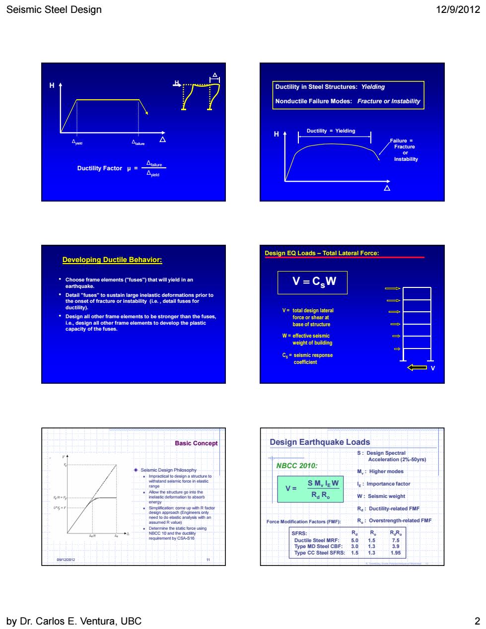
Seismic Steel Design 12/9/2012 by Dr. Carlos E. Ventura, UBC 2 H H ∆yield ∆failure Ductility Factor μ = ∆failure ∆yield H Ductility = Yielding Failure = Fracture or Instability Ductility in Steel Structures: Yielding Nonductile Failure Modes: Fracture or Instability Developing Ductile Behavior: • Choose frame elements ("fuses") that will yield in an earthquake. • Detail "fuses" to sustain large inelastic deformations prior to the onset of fracture or instability (i.e. , detail fuses for ductility). • Design all other frame elements to be stronger than the fuses, i.e., design all other frame elements to develop the plastic capacity of the fuses. Design EQ Loads – Total Lateral Force: V C Ws V = total design lateral force or shear at base of structure W = effective seismic weight of building CS = seismic response coefficient V 09/12/2012 11 Basic Concept Seismic Design Philosophy Impractical to design a structure to withstand seismic force in elastic range Allow the structure go into the inelastic deformation to absorb energy Simplification: come up with R factor design approach (Engineers only need to do elastic analysis with an assumed R value) Determine the static force using NBCC 10 and the ductility requirement by CSA-S16 Design Earthquake Loads R. Tremblay, Ecole Polytechnique of Montreal 12 NBCC 2010: V = S Mv IE W Rd Ro S : Design Spectral Acceleration (2%-50yrs) Mv : Higher modes IE : Importance factor W : Seismic weight Rd : Ductility-related FMF Ro : Overstrength-related FMF Rd Ro RdRo Ductile Steel MRF: 5.0 1.5 7.5 Type MD Steel CBF: 3.0 1.3 3.9 Type CC Steel SFRS: 1.5 1.3 1.95 SFRS: Force Modification Factors (FMF):
Seismic Steel Design 12/9/2012 ion factors in the 2010 RR=1.3 1.5△e Design EQ Loads-Total Lateral Force per ASCE7-05: V=CW (rA Tndanenpenodoiuen t年Tyha Tlong period transition perioc R=response modification coefficier R factors for Selected Stecl Systems (ASCE 7): trically Braced Frames): R-32 R= by Dr.Carlos E.Ventura,UBC 3
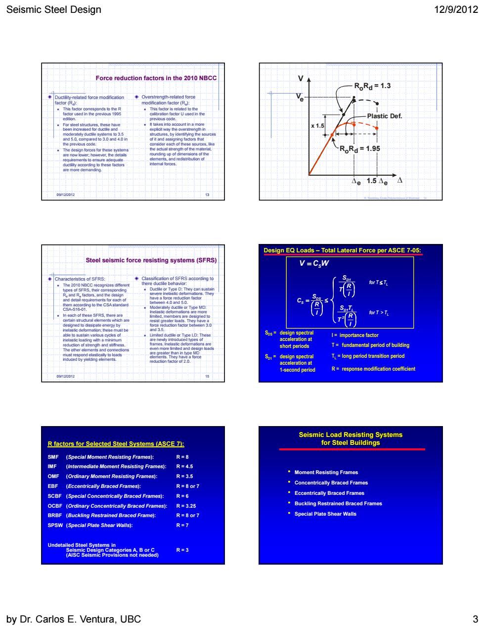
Seismic Steel Design 12/9/2012 by Dr. Carlos E. Ventura, UBC 3 09/12/2012 13 Overstrength-related force modification factor (Ro): This factor is related to the calibration factor U used in the previous code. It takes into account in a more explicit way the overstrength in structures, by identifying the sources of it and assigning factors that consider each of these sources, like the actual strength of the material, rounding up of dimensions of the elements, and redistribution of internal forces. Ductility-related force modification factor (Rd): This factor corresponds to the R factor used in the previous 1995 edition. For steel structures, these have been increased for ductile and moderately ductile systems to 3.5 and 5.0, compared to 3.0 and 4.0 in the previous code. The design forces for these systems are now lower; however, the details requirements to ensure adequate ductility according to these factors are more demanding. Force reduction factors in the 2010 NBCC V V 1.5 R R = 1.3 Plastic Def. e e e o d R R = 1.95 x 1.5 o d R. Tremblay, Ecole Polytechnique of Montreal 14 09/12/2012 15 Steel seismic force resisting systems (SFRS) Classification of SFRS according to there ductile behavior: Ductile or Type D: They can sustain severe inelastic deformations. They have a force reduction factor between 4.0 and 5.0. Moderately ductile or Type MD: Inelastic deformations are more limited, members are designed to resist greater loads. They have a force reduction factor between 3.0 and 3.5. Limited ductile or Type LD: These are newly introduced types of frames. Inelastic deformations are even more limited and design loads are greater than in type MD elements. They have a force reduction factor of 2.0. Characteristics of SFRS: The 2010 NBCC recognizes different types of SFRS, their corresponding Rd and Ro factors, and the design and detail requirements for each of them according to the CSA standard CSA-S16-01. In each of these SFRS, there are certain structural elements which are designed to dissipate energy by inelastic deformation; these must be able to sustain various cycles of inelastic loading with a minimum reduction of strength and stiffness. The other elements and connections must respond elastically to loads induced by yielding elements. Design EQ Loads – Total Lateral Force per ASCE 7-05: SDS = design spectral acceleration at short periods SD1 = design spectral acceleration at 1-second period I = importance factor R = response modification coefficient T = fundamental period of building V CSW I R S C DS S I R T SD1 I R T S T 2 D1 L for T TL for T > TL TL = long period transition period R factors for Selected Steel Systems (ASCE 7): SMF (Special Moment Resisting Frames): R = 8 IMF (Intermediate Moment Resisting Frames): R = 4.5 OMF (Ordinary Moment Resisting Frames): R = 3.5 EBF (Eccentrically Braced Frames): R = 8 or 7 SCBF (Special Concentrically Braced Frames): R = 6 OCBF (Ordinary Concentrically Braced Frames): R = 3.25 BRBF (Buckling Restrained Braced Frame): R = 8 or 7 SPSW (Special Plate Shear Walls): R = 7 Undetailed Steel Systems in Seismic Design Categories A, B or C R = 3 (AISC Seismic Provisions not needed) Seismic Load Resisting Systems for Steel Buildings • Moment Resisting Frames • Concentrically Braced Frames • Eccentrically Braced Frames • Buckling Restrained Braced Frames • Special Plate Shear Walls

Seismic Steel Design 12/9/2012 自 Clause 27 of CSA-S16-01 Seismic design requirements search Kobe1995 SIGNIFICANT REVISIONS MOMENT RESISTING FRAME (MRF) 27 Seismic Design Requirements or mechanisms are designed to r this Cae他eteyPimarnwyieunalyelding ergy dissipati to b nic loads High Ductiityand aft isadvanta9道 are transmitted to the foundation. ·Low lastic Stiffness Moment Resisting Fram by Dr.Carlos E.Ventura,UBC
Seismic Steel Design 12/9/2012 by Dr. Carlos E. Ventura, UBC 4 9 December 2012 19 Clause 27 of CSA-S16-01 Seismic design requirements 9 December 2012 20 Northridge 1994 Kobe 1995 SIGNIFICANT REVISIONS Research 9 December 2012 21 27. Seismic Design Requirements Capacity Design: • Specific elements or mechanisms are designed to dissipate energy; • All other elements are sufficiently strong for this energy dissipation to be achieved; • Structural integrity is maintained; • Elements and connections in the horizontal and vertical load paths are designed to resist these seismic loads; • Diaphragms and collector elements are capable of transmitting the loads developed at each level to the vertical lateral-load-resisting system; and, • These loads are transmitted to the foundation. MOMENT RESISTING FRAME (MRF) Advantages • Architectural Versatility • High Ductility and Safety Disadvantages • Low Elastic Stiffness Beams and columns with moment resisting connections; resist lateral forces by flexure and shear in beams and columns - i.e. by frame action. Develop ductility primarily by flexural yielding of the beams: Moment Resisting Frame

Seismic Steel Design 12/9/2012 27.Seismic Design Requirements nt-Resisting fran D(ductile moment-resisting frames,R=5) with limited ductiity,R=2) 用用 Type D&Type MD-Inelastic Response by Dr.Carlos E.Ventura,UBC 5」
Seismic Steel Design 12/9/2012 by Dr. Carlos E. Ventura, UBC 5 Inelastic Response of a Steel Moment Resisting Frame 9 December 2012 28 27. Seismic Design Requirements Moment-Resisting Frames • Type D (ductile moment-resisting frames, R = 5 ) • Type MD (moderately ductile, R = 3.5 ) • Type LD ( frames with limited ductility, R = 2 ) 9 December 2012 29 Type D & Type MD - Inelastic Response PLASTIC HINGE (typ.) 9 December 2012 30 Moment Connections for Seismic Applications by CISC Reduced beam section Bolted end plate - 8 bolts Bolted stiffened end plate – 16 bolts