
800 Figure 13-14 The CCT diagram(solid 咖 lines)for a 1080 steel compared with the TTΠ diagram(dashed lines). 600 500 400 300 M 200 M 100 Martensite Pearlite Fine Coarse martensite Pearlite pearlite 0.1 10 102 103 104 105 106 Time(s)
2.4.2 钢在冷却时的转变 2、过冷A的连续冷却转变 (1)共析钢过冷A的连续 冷却转变—CCT曲线 上临界冷却速度Vk 下临界冷却速度Vk ’ 共析钢CCT曲线与C曲线的比较 CCT曲线中没有A转变为B的部分 CCT曲线位于C曲线的右下方 共析钢CCT曲线 连续冷却转变 Continuous Cooling Transformation 2.4 钢的热处理(heat treatment of steels)
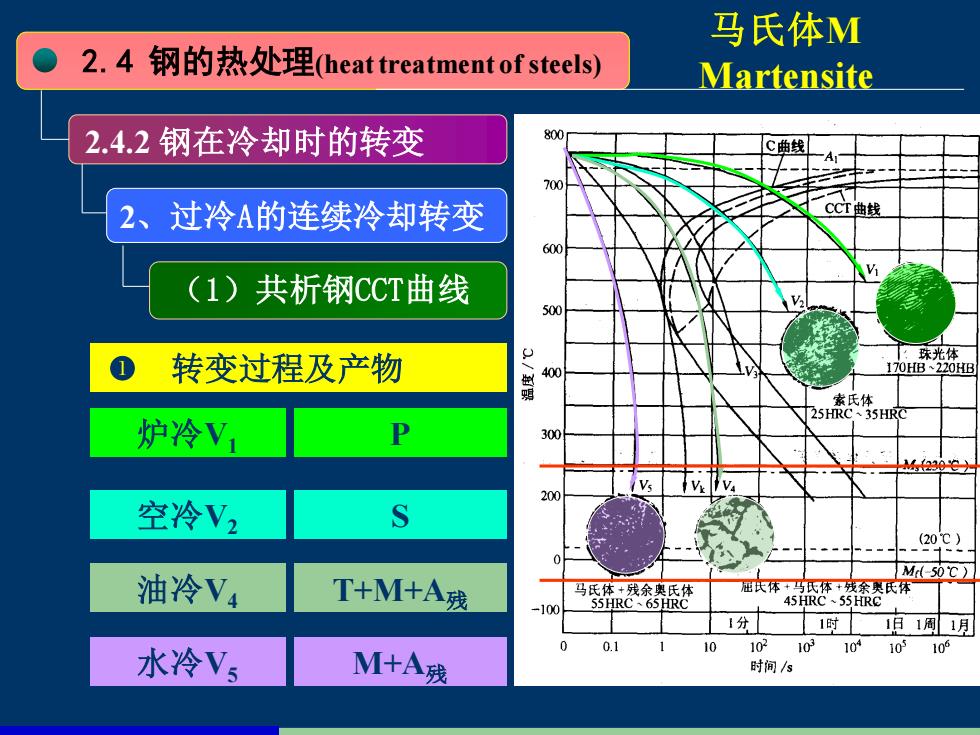
马氏体M 2.4钢的热处理heat treatment of steels) Martensite 2.4.2钢在冷却时的转变 800 C曲线 700 2、过冷A的连续冷却转变 CCT曲线 600 (1)共析钢CCT曲线 500 :珠光体 1 转变过程及产物 170HB~220HB 明 素氏体 25HRC、35HRC 炉冷V1 P 300 M30 Vs 200 空冷V2 S .202 Ml-50℃) 油冷V4 T+M+A残 马氏体+残余奥氏体 屈氏体+马氏体+残余奥氏 45HRC 55HRC 100 55HRC、65HRC 1分 1时1日1周1月 水冷Vs 0.1 10 102103 10410510 M+A残 时间/s
2.4 钢的热处理(heat treatment of steels) 2.4.2 钢在冷却时的转变 2、过冷A的连续冷却转变 (1)共析钢CCT曲线 转变过程及产物 炉冷V1 空冷V2 油冷V4 水冷V5 P S T+M+A残 M+A残 马氏体M Martensite
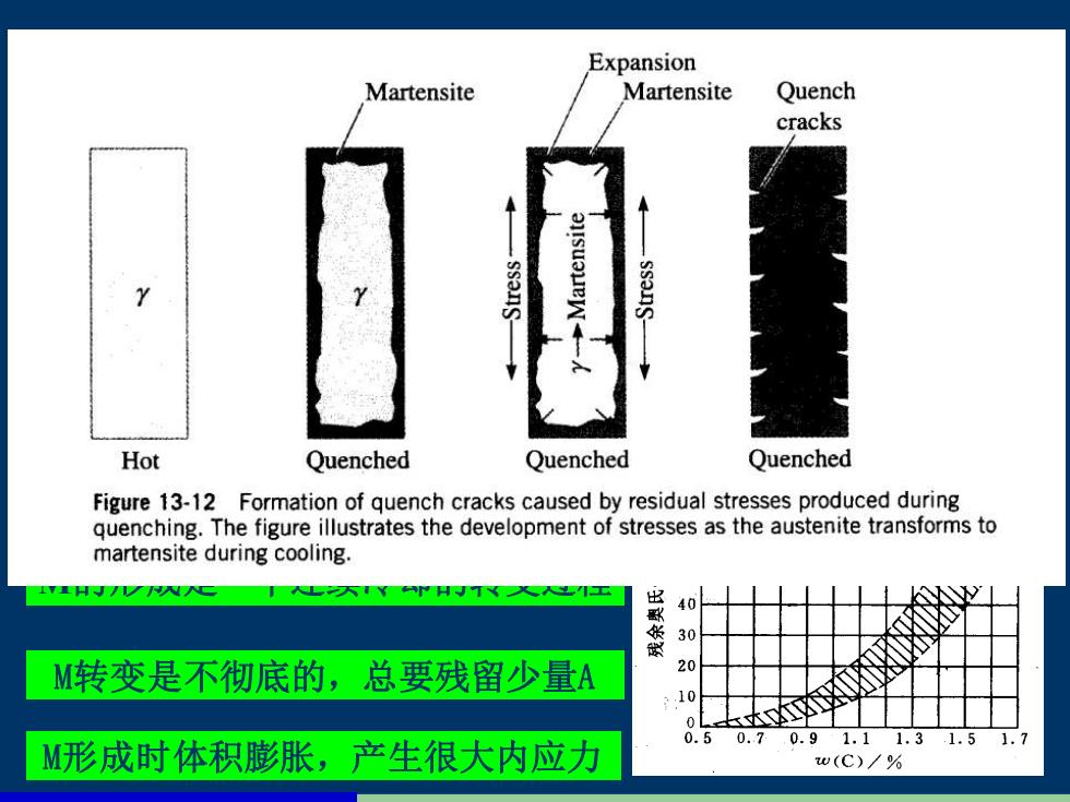
Expansion Martensite Martensite Quench cracks Hot Quenched Quenched Quenched Figure 13-12 Formation of quench cracks caused by residual stresses produced during quenching.The figure illustrates the development of stresses as the austenite transforms to martensite during cooling. 40 30 M转变是不彻底的,总要残留少量A 20 10 0.5 女举 0.7 0.91.11.31.51.7 M形成时体积膨胀,产生很大内应力 w(C)/%
2.4 钢的热处理(heat treatment of steels) 2.4.2 钢在冷却时的转变 2、过冷A的连续冷却转变 M(Martensite)转变的特点 过冷A转变为M是一种非扩散型转变 M的形成是一个连续冷却的转变过程 M转变是不彻底的,总要残留少量A M形成时体积膨胀,产生很大内应力 (1)共析钢CCT曲线 M为C过饱和的F