Experiment 1:Diffraction from a Single slit EQUIPMENT REQUIRED -Track and screen from the Basic Optics System(OS-85 1 5) Diode Laser (OS-8525) Single Slit Disk(OS-8523) -white paper to cover screen metric rule Purpose The purpose of this experiment is to examine the diffraction pattern formed by laser light passing through a single slit and verify that the positions of the minima in the diffraction pattern match the positions predicted by theory. Theory When diffraction of light occurs as it passes through a slit,the angle to the minima in the diffraction pattern is given by asin0=m2(m=1,2,3,..) Where a is the slit width,0 is the angle from the center of the pattern to the m minimum, A is the wavelength of the light,and m is the order (1 for the first minimum,2 for the second minimum,counting from the center out).See Figure 1.1.Since the angles are usually small,it can be assumed that sin0≈tan0 From trigonometry, creen tan0=上 Figure 1.1:Single Slit Diffraction Pattern D Where y is the distance on the screen from the center of the pattern to the m minimum and D is the distance from the slit to the screen as shown in Figure 1.1.The diffraction equation can thus be solved for the slit width: a=mi -(m=1,2,3…) y
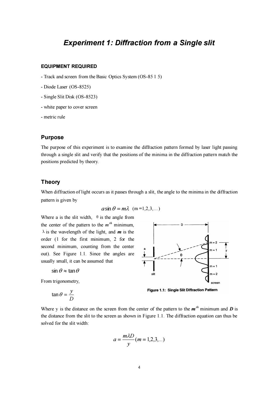
4 Experiment 1: Diffraction from a Single slit EQUIPMENT REQUIRED - Track and screen from the Basic Optics System (OS-85 1 5) - Diode Laser (OS-8525) - Single Slit Disk (OS-8523) - white paper to cover screen - metric rule Purpose The purpose of this experiment is to examine the diffraction pattern formed by laser light passing through a single slit and verify that the positions of the minima in the diffraction pattern match the positions predicted by theory. Theory When diffraction of light occurs as it passes through a slit, the angle to the minima in the diffraction pattern is given by asin = m (m =1,2,3,…) Where a is the slit width, θis the angle from the center of the pattern to the m th minimum, λis the wavelength of the light, and m is the order (1 for the first minimum, 2 for the second minimum, counting from the center out). See Figure 1.1. Since the angles are usually small, it can be assumed that sin tan From trigonometry, D y tan = Where y is the distance on the screen from the center of the pattern to the m th minimum and D is the distance from the slit to the screen as shown in Figure 1.1. The diffraction equation can thus be solved for the slit width: = (m = 1,2,3,...) y m D a
Setup 1.Set up the laser at one end of the optics bench and place the Single Slit Disk in its holder about 3 cm in front of the laser.See Figure 1.2. 2.Cover the screen with a sheet of paper and attach it to the other end of the bench so that the paper faces the laser. 3.Select the 0.04 mm slit by rotating the slit disk until the 0.04 mm slit is centered in the slit holder. Adjust the position of the laser beam from left-to-right and up-and-down until the beam is centered on the slit. screen Figure 1.2:Optics Bench Setup Procedure 1.Determine the distance from the slit to the screen.Note that the slit is actually offset from the center line of the slit holder.Record the screen position,slit position,and the difference between these (the skit-to-screen distance)in Table 1.1. 2.Turn off the room lights and mark the positions of the minima in the diffraction pattern on the screen. 3.Turn on the room lights and measure the distance between the first order (m=1)marks and record this distance in 1.1.Also measure the distance between the second order(m =2)marks and record in Table 1.1. Table 1.1:Data and Results for the 0.04-mm Single Slit Slit-to-screen distance(D)= First Order(m=1) Second Order(m=2) Distance between Side orders Distance from center to side (y) Calculated slit width difference
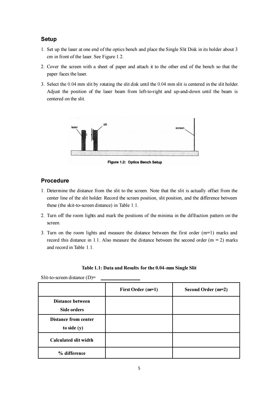
5 Setup 1. Set up the laser at one end of the optics bench and place the Single Slit Disk in its holder about 3 cm in front of the laser. See Figure 1.2. 2. Cover the screen with a sheet of paper and attach it to the other end of the bench so that the paper faces the laser. 3. Select the 0.04 mm slit by rotating the slit disk until the 0.04 mm slit is centered in the slit holder. Adjust the position of the laser beam from left-to-right and up-and-down until the beam is centered on the slit. Procedure 1. Determine the distance from the slit to the screen. Note that the slit is actually offset from the center line of the slit holder. Record the screen position, slit position, and the difference between these (the skit-to-screen distance) in Table 1.1. 2. Turn off the room lights and mark the positions of the minima in the diffraction pattern on the screen. 3. Turn on the room lights and measure the distance between the first order (m=1) marks and record this distance in 1.1. Also measure the distance between the second order (m = 2) marks and record in Table 1.1. Table 1.1: Data and Results for the 0.04-mm Single Slit Slit-to-screen distance (D)= First Order (m=1) Second Order (m=2) Distance between Side orders Distance from center to side (y) Calculated slit width % difference