
Example 6.4 Consider the simple mixer shown in Fig.6.14(a).Assuming RL>Rs and the Lo has a 50%duty cycle,determine the output noise spectrum due to Rs,i.e.,assume RL is noiseless. Figure 6.14.(a)Passive mixer,(b)input and output signals in time and frequency domains. [View full size image] (a) 工, 2kTRs 2kTRs 米、 +3fLo -1o0+1Lo (b)
Example 6.4
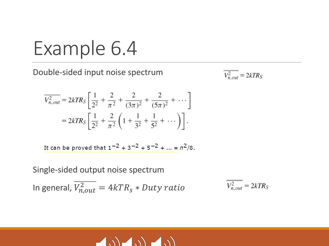
Example 6.4 Double-sided input noise spectrum Vi.ow =2KTRs V=2kTR +品+品+… 2”女2、 =2KTR [皮+(+京++…小 It can be proved that 1-2+3-2+5-2+...=n2/8. Single-sided output noise spectrum In general,Vout=4kTRs Duty ratio Vh.oMt=2kTRs 1
Example 6.4 Double-sided input noise spectrum Single-sided output noise spectrum In general, �!,#$% & = 4���' ∗ ���� �����

6.1.3.Single-Balanced and Double-Balanced Mixers Figure 6.15.(a)Single-balanced passive mixer,(b)implementation of (a). CGS1 CGDI out1 RL M Vaf M2 out2 (a (b) suffers from significant LO-IF feedthrough
6.1.3. Single-Balanced and Double-Balanced Mixers suffers from significant LO-IF feedthrough

6.1.3.Single-Balanced and Double-Balanced Mixers Figure 6.16.Double-balanced passive mixer. M R Voutt 行 VLO
6.1.3. Single-Balanced and Double-Balanced Mixers
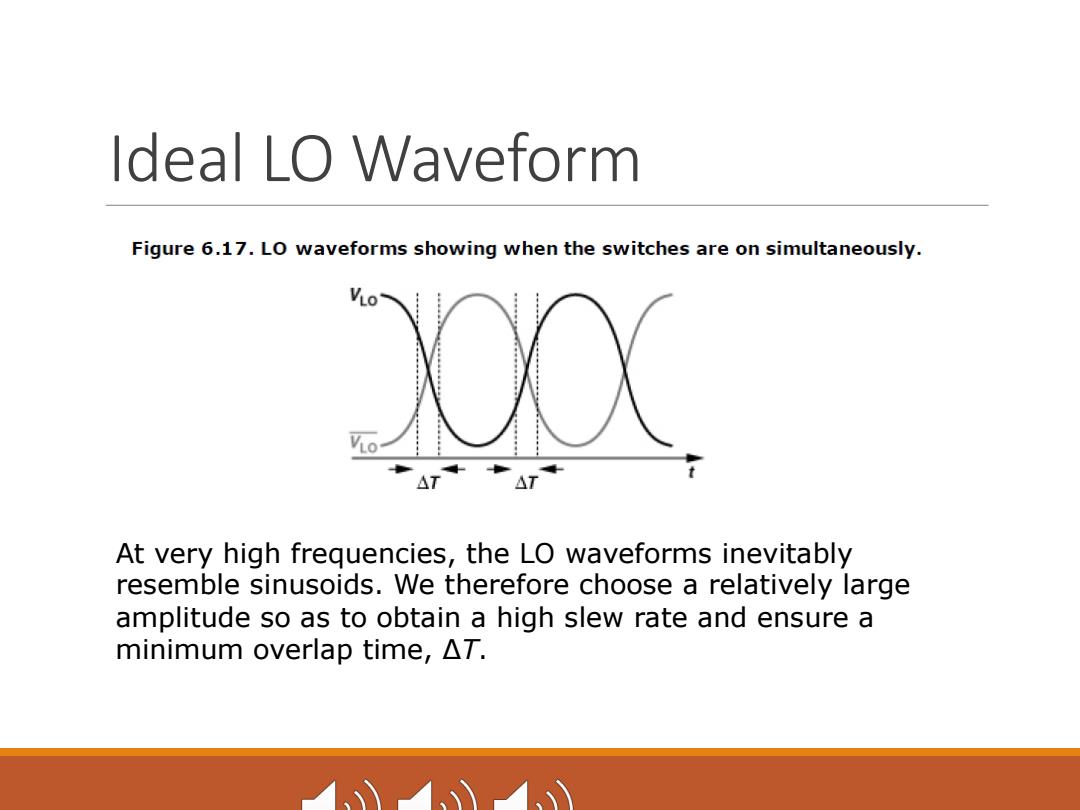
Ideal LO Waveform Figure 6.17.LO waveforms showing when the switches are on simultaneously. 200( At very high frequencies,the LO waveforms inevitably resemble sinusoids.We therefore choose a relatively large amplitude so as to obtain a high slew rate and ensure a minimum overlap time,AT
Ideal LO Waveform At very high frequencies, the LO waveforms inevitably resemble sinusoids. We therefore choose a relatively large amplitude so as to obtain a high slew rate and ensure a minimum overlap time, ΔT