Transmission through a wall (5/5) For power conservation we have: Simel =Srem+S rasm Sinel Smel Spusm-1-Fom Sincl Now the transmitted power at the first interface,properly multiplied by the lossy-medium attenuation factor becomes the incident power at the second interface,therefore we have --f S ransm2 le=1-rP Thus: e2aw Sincl 2
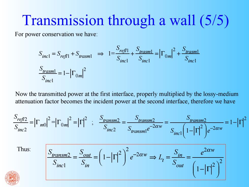
Transmission through a wall (5/5) Sinc1 = Srefl1 + Strasm1 ⇒ 1= Srefl1 Sinc1 + Strasm1 Sinc1 = Γ0m 2 + Strasm1 Sinc1 Strasm1 Sinc1 = 1− Γ0m 2 Srefl2 Sinc2 = Γm0 2 = Γ0m 2 = Γ 2 ; Stransm2 Sinc2 = Stransm2 Stransm1e−2αw = Stransm2 Sinc1 1− Γ ⎛ 2 ⎝ ⎜ ⎞ ⎠ ⎟ e−2αw = 1− Γ 2 Stransm2 Sinc1 = Sout Sin = 1− Γ ⎛ 2 ⎝ ⎜ ⎞ ⎠ ⎟ 2 e−2αw ⇒ Lt = Sin Sout = e 2αw 1− Γ ⎛ 2 ⎝ ⎜ ⎞ ⎠ ⎟ 2 For power conservation we have: Now the transmitted power at the first interface, properly multiplied by the lossy-medium attenuation factor becomes the incident power at the second interface, therefore we have Thus:
Example of Transmission Loss Brick wall:8'=4,8"=0.2,w=20 cm r1w9an 0.2π at1,800MHz(2,=1/6m):0= ==1.88 (1/6)N L,==1-0.11e20a0=27or43aB (Source:Prof.H.L.Bertoni)
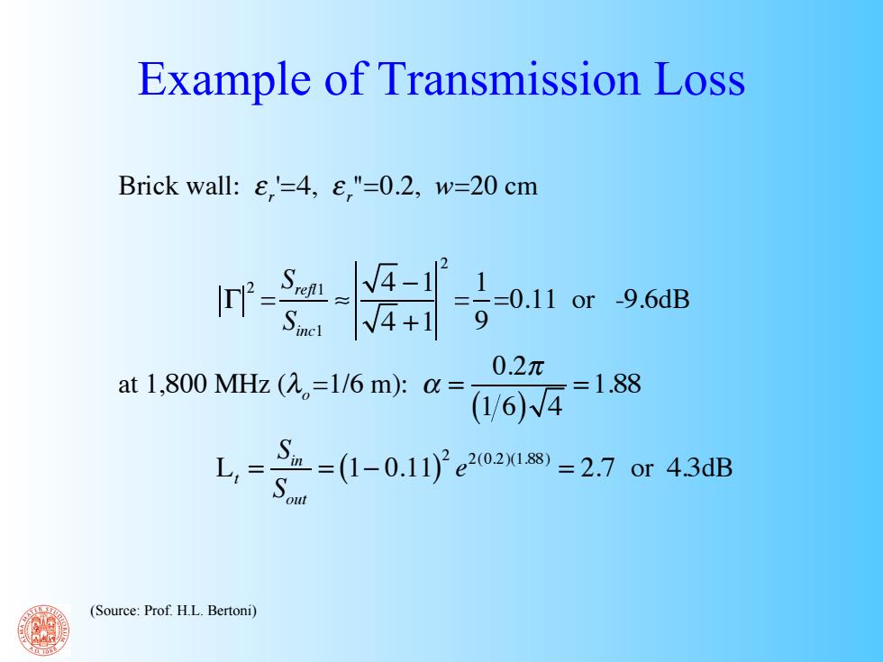
Example of Transmission Loss Brick wall: ε r ' =4, ε r " =0.2, w=20 cm Γ 2 = Srefl1 Sinc1 ≈ 4 −1 4 +1 2 = 1 9 =0.11 or -9.6dB at 1,800 MHz (λo =1/6 m): α = 0.2π (1 6) 4 = 1.88 Lt = Sin Sout = (1− 0.11) 2 e 2(0.2)(1.88) = 2.7 or 4.3dB (Source: Prof. H.L. Bertoni)
Summary of Reflection and Transmission Loss Theory Wall Type Frequency Band Ref.loss Trans.Loss Brick,exterior 1.8-4GHz 10 dB 10 dB Concrete block,interior 2.4 GHz 5 dB Gypsum board,interior 3.4 GHz 4dB 2 dB Measured Exterior frame 800 MHz 4-7dB 5-6 GHz 9-18dB with metal siding 5 GHz 36 dB Brick,exterior 4-6 GHz 10 dB 14 dB Concrete block,interior 2.4/5GHz 5/5-10dB Gypsum board,interior 2.4/5GHz 3/5dB Wooden floors 5 GHz 9 dB Concrete floors 900 MHz 13 dB (Source:Prof.H.L.Bertoni)
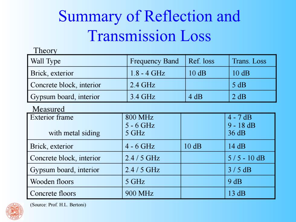
Summary of Reflection and Transmission Loss Wall Type Frequency Band Ref. loss Trans. Loss Brick, exterior 1.8 - 4 GHz 10 dB 10 dB Concrete block, interior 2.4 GHz 5 dB Gypsum board, interior 3.4 GHz 4 dB 2 dB Theory Measured Exterior frame with metal siding 800 MHz 5 - 6 GHz 5 GHz 4 - 7 dB 9 - 18 dB 36 dB Brick, exterior 4 - 6 GHz 10 dB 14 dB Concrete block, interior 2.4 / 5 GHz 5 / 5 - 10 dB Gypsum board, interior 2.4 / 5 GHz 3 / 5 dB Wooden floors 5 GHz 9 dB Concrete floors 900 MHz 13 dB (Source: Prof. H.L. Bertoni)
Geometrical Theory of Diffraction The extension of GO to the category of diffracted rays was first introduced by J.B.Keller in 1961 and is based on the following assumptionst61: I.A diffracted ray is generated whenever a ray impinges on an edge (or on a vertex) II.For every diffracted ray the Fermat's principle holds Diffraction law:the angles between incident diffracted ray and the edge satisfy "Snell's law applied to diffraction": Keller's nsine;=na.sined cone If the rays are in the same material then:00 Therefore diffracted rays ouside the wedge belong to the Keller's cone Incident ray
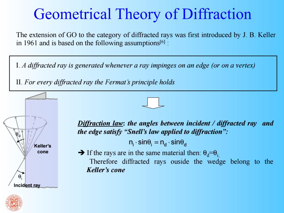
The extension of GO to the category of diffracted rays was first introduced by J. B. Keller in 1961 and is based on the following assumptions[6] : I. A diffracted ray is generated whenever a ray impinges on an edge (or on a vertex) II. For every diffracted ray the Fermat’s principle holds Incident ray Keller’s cone Diffraction law: the angles between incident / diffracted ray and the edge satisfy “Snell’s law applied to diffraction”: If the rays are in the same material then: θd=θi; Therefore diffracted rays ouside the wedge belong to the Keller’s cone ni sin i nd sinθd ⋅ θ = ⋅ Geometrical Theory of Diffraction θd θi