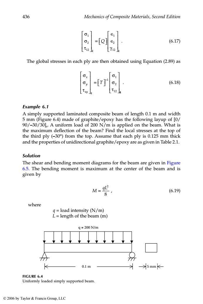
436 Mechanics of Composite Materials,Second Edition =[ (6.17) Y12 The global stresses in each ply are then obtained using Equation(2.89)as 61 =[r (6.18) Example 6.1 A simply supported laminated composite beam of length 0.1 m and width 5 mm(Figure 6.4)made of graphite/epoxy has the following layup of [0/ 90/-30/30].A uniform load of 200 N/m is applied on the beam.What is the maximum deflection of the beam?Find the local stresses at the top of the third ply(-30)from the top.Assume that each ply is 0.125 mm thick and the properties of unidirectional graphite/epoxy are as given in Table 2.1. Solution The shear and bending moment diagrams for the beam are given in Figure 6.5.The bending moment is maximum at the center of the beam and is given by M92 8 (6.19) where g=load intensity (N/m) L=length of the beam(m) q=200N/m 77 0.1m >5mm FIGURE 6.4 Uniformly loaded simply supported beam. 2006 by Taylor Francis Group,LLC
436 Mechanics of Composite Materials, Second Edition . (6.17) The global stresses in each ply are then obtained using Equation (2.89) as . (6.18) Example 6.1 A simply supported laminated composite beam of length 0.1 m and width 5 mm (Figure 6.4) made of graphite/epoxy has the following layup of [0/ 90/–30/30]s. A uniform load of 200 N/m is applied on the beam. What is the maximum deflection of the beam? Find the local stresses at the top of the third ply (–30°) from the top. Assume that each ply is 0.125 mm thick and the properties of unidirectional graphite/epoxy are as given in Table 2.1. Solution The shear and bending moment diagrams for the beam are given in Figure 6.5. The bending moment is maximum at the center of the beam and is given by , (6.19) where q = load intensity (N/m) L = length of the beam (m) FIGURE 6.4 Uniformly loaded simply supported beam. σ σ τ γ 1 2 12 1 2 12 ⎡ ⎣ ⎢ ⎢ ⎢ ⎤ ⎦ ⎥ ⎥ ⎥ = ⎡ ⎣ ⎤ ⎦ ∈ ∈ ⎡ ⎣ ⎢ ⎢ ⎢ ⎤ ⎦ ⎥ ⎥ ⎥ k k Q σ σ τ σ σ τ x y xy k T ⎡ ⎣ ⎢ ⎢ ⎢ ⎤ ⎦ ⎥ ⎥ ⎥ = ⎡ ⎣ ⎤ ⎦ ⎡ ⎣ ⎢ ⎢ ⎢ ⎤ ⎦ ⎥ ⎥ ⎥ −1 1 2 12 k M qL = 2 8 5 mm q = 200 N/m 0.1 m 1343_book.fm Page 436 Tuesday, September 27, 2005 11:53 AM © 2006 by Taylor & Francis Group, LLC
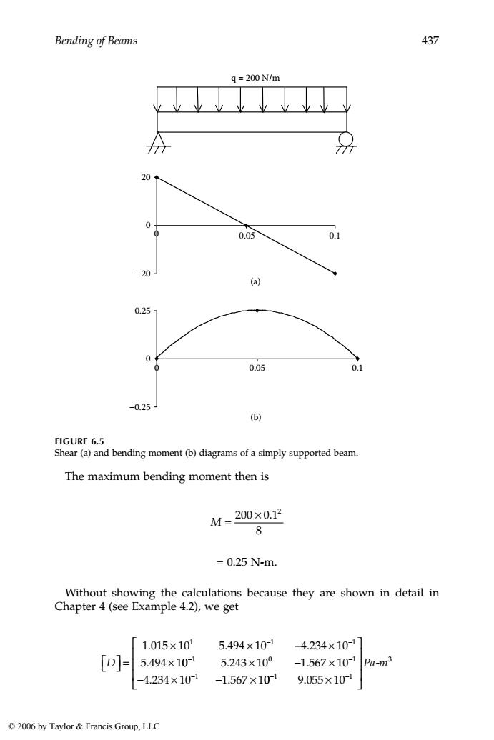
Bending of Beams 437 q=200N/m 20 0.05 0.1 -20 (a) 0.25 0 0.05 0.1 -0.25J (b) FIGURE 6.5 Shear(a)and bending moment(b)diagrams of a simply supported beam. The maximum bending moment then is M=200×0.12 8 =0.25N-m. Without showing the calculations because they are shown in detail in Chapter 4(see Example 4.2),we get 1.015×10 5.494×10 -4.234×10-1 [D]- 5.494×101 5.243×10° -1.567×10- Pa-m3 -4.234×10⁻¹ -1.567×10⁻¹ 9.055×101 2006 by Taylor Francis Group,LLC
Bending of Beams 437 The maximum bending moment then is = 0.25 N-m. Without showing the calculations because they are shown in detail in Chapter 4 (see Example 4.2), we get FIGURE 6.5 Shear (a) and bending moment (b) diagrams of a simply supported beam. q = 200 N/m (b) (a) 0 0 20 −20 0.05 0.1 0.25 0 0 0.05 0.1 −0.25 M = 200 × 0 1 8 2 . ⎡ ⎣D⎤ ⎦ = × × − × × − − 1 015 10 5 494 10 4 234 10 5 494 1 1 1 1 . . . . 0 5 243 10 1 567 10 4 234 10 1 567 1 1 0 1 1 − − − × − × − × − × . . . . 0 9 055 10 1 1 3 − − × ⎡ ⎣ ⎢ ⎢ ⎢ ⎤ ⎦ ⎥ ⎥ ⎥ . Pa-m 1343_book.fm Page 437 Tuesday, September 27, 2005 11:53 AM © 2006 by Taylor & Francis Group, LLC
438 Mechanics of Composite Materials,Second Edition 1.009×10 -9.209×10-3 4.557×10⁻²¹ [D' -9.209×10⁻³ 1.926×10⁻¹ 2.901×10⁻² 4.557×10² 2.901×10⁻² 1.131×10° Pa-m3 To find the maximum deflection of the beam,6,we use the isotropic beam formula: 6-5qL (6.20) 384E,I Now,in Equation(6.12), h=(8)0.125×10) =0.001m D1=1.009×10⁻¹¹ Pa-m3 Thus, 12 ExDi 12 (0.0011.009×10 =1.189×101Pa From Equation(6.13), 13 12 _(5×10³)0.001)月 12 =4.167×10⁻¹³m4 2006 by Taylor Francis Group,LLC
438 Mechanics of Composite Materials, Second Edition . To find the maximum deflection of the beam, δ, we use the isotropic beam formula: . (6.20) Now, in Equation (6.12), . Thus, From Equation (6.13), ⎡ ⎣D⎤ ⎦ = × − × × − − − − 1 1 3 2 1 009 10 9 209 10 4 557 10 9 20 . . . . 9 10 1 926 10 2 901 10 4 557 10 2 901 3 1 2 2 × × × × × − − − − . . . . 10 1 131 10 1 2 0 3 − × ⎡ ⎣ ⎢ ⎢ ⎢ ⎤ ⎦ ⎥ ⎥ ⎥ . Pa-m δ = 5 384 4 qL E Ix h = ( )( ) × − 8 0 125 10 3 . = 0.001m D Pa m 11 1 3 1 009 10 ∗ − 1 = × − . E h D x = = ( ) ( ) × = × ∗ − 12 12 0 001 1 009 10 1 189 10 3 11 3 1 . . . 11Pa I bh m = = ( ) × ( ) = × − − 3 3 3 13 4 12 5 10 0 001 12 4 167 10 . . . 1343_book.fm Page 438 Tuesday, September 27, 2005 11:53 AM © 2006 by Taylor & Francis Group, LLC

Bending of Beams 439 Therefore,from Equation (6.20), 6= (⑤)(200)(0.1° (3841.189×104.167×10-8 =5.256×10⁻³m =5.256171m. The maximum curvature is at the middle of the beam and is given by Di Di2 9L2 Xy 8b Die 1.009×101 -9.209×10⁻³ 200×0.12 4.557×10⁻² 8×0.005 1.009×10⁻¹¹ -9.209×10⁻³ 50 4.557×10⁻² 5.045 1 -0.4605 m 2.279 The global strains(Equation 6.15)at the top of the third ply(-30)are Ex Kx ∈y =Z Yw] 5.045 =(-0.00025 -0.4605 2.279 2006 by Taylor Francis Group,LLC
Bending of Beams 439 Therefore, from Equation (6.20), . The maximum curvature is at the middle of the beam and is given by . The global strains (Equation 6.15) at the top of the third ply (–30°) are δ = ( )( )( ) ( )( ) × × − 5 200 0 1 384 1 189 10 4 167 10 4 11 1 . . . 3 ( ) = × − 5 256 10 3 . m = 5.256 mm χ χ χ x y xy D D D qL ⎡ ⎣ ⎢ ⎢ ⎢ ⎤ ⎦ ⎥ ⎥ ⎥ = ⎡ ⎣ ⎢ ⎢ ⎢ ⎤ ⎦ ⎥ ⎥ ⎥ ∗ ∗ ∗ 11 12 16 2 8b = × − × × ⎡ ⎣ ⎢ ⎢ ⎢ ⎤ ⎦ ⎥ ⎥ ⎥ − − − 1 009 10 9 209 10 4 557 10 2 1 3 2 . . . 00 0 1 8 0 005 2 × × . . = × − × × ⎡ ⎣ ⎢ ⎢ ⎢ ⎤ ⎦ ⎥ ⎥ ⎥ − − − 1 009 10 9 209 10 4 557 10 5 1 3 2 . . . 0 = − ⎡ ⎣ ⎢ ⎢ ⎢ ⎤ ⎦ ⎥ ⎥ ⎥ 5 045 0 4605 2 279 1 . . . m ∈ ∈ ⎡ ⎣ ⎢ ⎢ ⎢ ⎤ ⎦ ⎥ ⎥ ⎥ = ⎡ ⎣ ⎢ ⎢ ⎢ ⎤ ⎦ ⎥ ⎥ ⎥ x y xy x y xy z γ κ κ κ = −( ) − ⎡ ⎣ ⎢ ⎢ ⎢ ⎤ ⎦ ⎥ ⎥ ⎥ 0 00025 5 045 0 4605 2 279 . . . . 1343_book.fm Page 439 Tuesday, September 27, 2005 11:53 AM © 2006 by Taylor & Francis Group, LLC