
Name. Class _Student No」 Date Ex.3-2 For the position shown of a geared linkage,determine graphically the ratio 3/of the angular velocity of gear 3 to that of gear 1,using the method of instant centres. H 6 Ex.3-3 For the position shown of cam mechanism,determine graphically the ratio 2/of the angular velocity of follower 2 to that of cam 1,using the method of instant centres 3 0
11 Name Class Student No. Date Ex.3-2 For the position shown of a geared linkage, determine graphically the ratio 3/1 of the angular velocity of gear 3 to that of gear 1, using the method of instant centres. Ex.3-3 For the position shown of cam mechanism, determine graphically the ratio 2/1 of the angular velocity of follower 2 to that of cam 1, using the method of instant centres. ω1 1 3 2 O 6 1 2 3 4 5 A B C D E F
Name Class Student No. Date Ex.3-4 In the pivot four-bar linkage shown below,1=-10rad/sec.Using the method of instant centers graphically, (a)find the velocity of point C for the position shown. (b)for the position shown,locate point E on the line BC(or its extension)which has the minir um velocity among all the points on line BC and its extension, and then calculate its velocity. (c)draw two positions of crank AB correspond ing to Vc=0. 2 3 4 777777
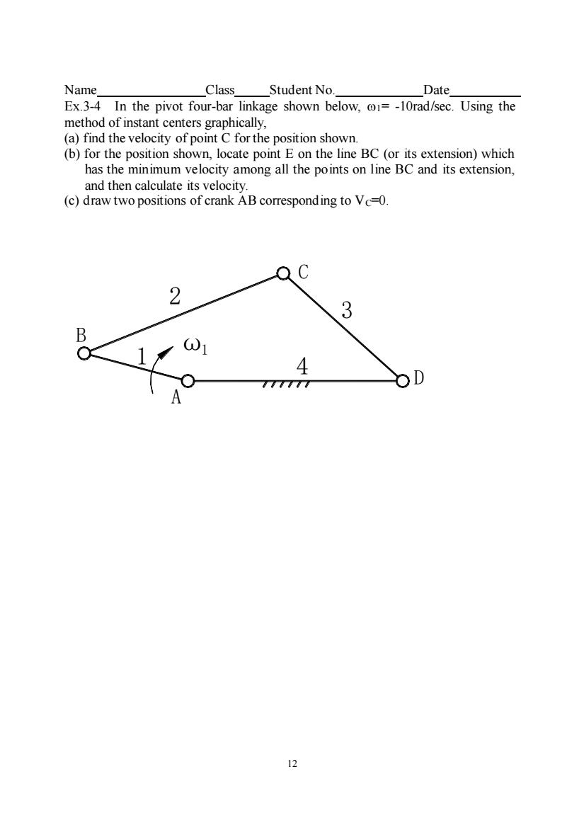
12 Name Class Student No. Date Ex.3-4 In the pivot four-bar linkage shown below, 1= -10rad/sec. Using the method of instant centers graphically, (a) find the velocity of point C for the position shown. (b) for the position shown, locate point E on the line BC (or its extension) which has the minimum velocity among all the points on line BC and its extension, and then calculate its velocity. (c) draw two positions of crank AB corresponding to VC=0. B A 1 ω1 4 2 3 D C

Name. Class Student No」 Date. Ex.3-5 In the six-bar mechanism shown below,XA=0,YA=0,XD=450mm,YD=0, LAB=150mm,LBc=400mm,LDc=350mm,∠CDE=30°,LDE=150mm,LE=400mm Crank AB rotates a a constant speed 10rad/sec.A main program is required to analyze the output motions of the point F.The mechanism will be analyzed for the whole cycle when the driver AB rotates from0°to360°with a step size of△0i=5°. 2 13
13 Name Class Student No. Date Ex.3-5 In the six-bar mechanism shown below, XA=0, YA=0, XD=450mm, YD=0, LAB=150mm, LBC=400mm, LDC=350mm, CDE=30, LDE=150mm, LEF=400mm. Crank AB rotates at a constant speed 10rad/sec. A main program is required to analyze the output motions of the point F. The mechanism will be analyzed for the whole cycle when the driver AB rotates from 0 to 360 with a step size of 1 =5. A B C E F 2 3 4 5 ω θ1 1 6 D

Name Class Student No. Date Ex.3-6 The mechanism shown below has the following dimensions:XA=0.YA=0. XD=200mm,YD-.LAB=80mm.LcD-60mm and LBE-380mm.Crank AB rotates at a constant speed of 10rad/sec.A main program is required to analyze the output motions of the point E.The mechanism will be analyzed for the whole cycle when the driver BArotates from0°to360°with a step size of△0i=5o 1
14 Name Class Student No. Date Ex.3-6 The mechanism shown below has the following dimensions: XA=0, YA=0, XD=200mm, YD=0, LAB=80mm, LCD=60mm and LBE=380mm. Crank AB rotates at a constant speed of 10rad/sec. A main program is required to analyze the output motions of the point E. The mechanism will be analyzed for the whole cycle when the driver BA rotates from 0 to 360 with a step size of 1 =5. A C D E 2 3 4 θ ω 1 1

Name. Class _Student No. Date_ Ex3-7.In the mechanism shown below,XG=YG=0,XB=-42,YB=39,Xp=10, YD=75,LBA=23mm,LGF=12mm,LFE=95mm,LEC=69mm,LDC=48mm,ZEFG=90 Crank BA rotates at a constant speed of 10 rad/sec.A main program is required to analyze the output motions of the point C.The mechanism will be analyzed for the whole cycle when the driver BA rotates from 0 to 360 with a step size of A01=5. D G
15 Name Class Student No. Date Ex3-7 . In the mechanism shown below, XG=YG=0, XB= - 42, YB=39, XD=10, YD=75, LBA=23mm, LGF=12mm, LFE=95mm, LEC=69mm, LDC=48mm, EFG=90. Crank BA rotates at a constant speed of 10 rad/sec. A main program is required to analyze the output motions of the point C. The mechanism will be analyzed for the whole cycle when the driver BA rotates from 0 to 360 with a step size of 1 =5. G 6 D 6 B 6 E A C F 1 2 3 4 5