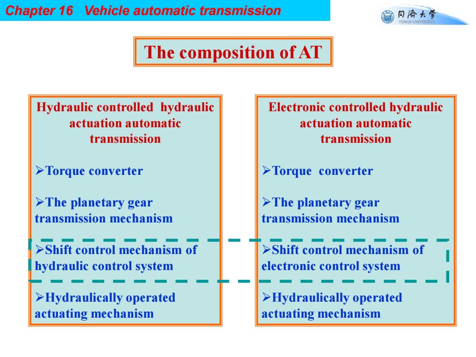
Chapter 16 Vehicle automatic transmission 同©大学 TONGII UNIVERSTTY The composition of AT Hydraulic controlled hydraulic Electronic controlled hydraulic actuation automatic actuation automatic transmission transmission >Torque converter >Torque converter >The planetary gear >The planetary gear transmission mechanism transmission mechanism >Shift control mechanism of >Shift control mechanism of hydraulic control system electronic control system >Hydraulically operated >Hydraulically operated actuating mechanism actuating mechanism
Chapter 16 Vehicle automatic transmission The composition of AT Hydraulic controlled hydraulic actuation automatic transmission Torque converter The planetary gear transmission mechanism Shift control mechanism of hydraulic control system Hydraulically operated actuating mechanism Electronic controlled hydraulic actuation automatic transmission Torque converter The planetary gear transmission mechanism Shift control mechanism of electronic control system Hydraulically operated actuating mechanism

Chapter 16 Vehicle automatic transmission 同©大学 TDNVE Section 2 Fluid Coupling and Torque Converter >The fluid coupling and torque converter all are dynamic fluid transmission >Hydrodynamic fluid transmission refers to the hydraulic transmission of power by the change in kinetic energy of the fluid in the circular flow process
Chapter 16 Vehicle automatic transmission The fluid coupling and torque converter all are dynamic fluid transmission Section 2 Fluid Coupling and Torque Converter Hydrodynamic fluid transmission refers to the hydraulic transmission of power by the change in kinetic energy of the fluid in the circular flow process
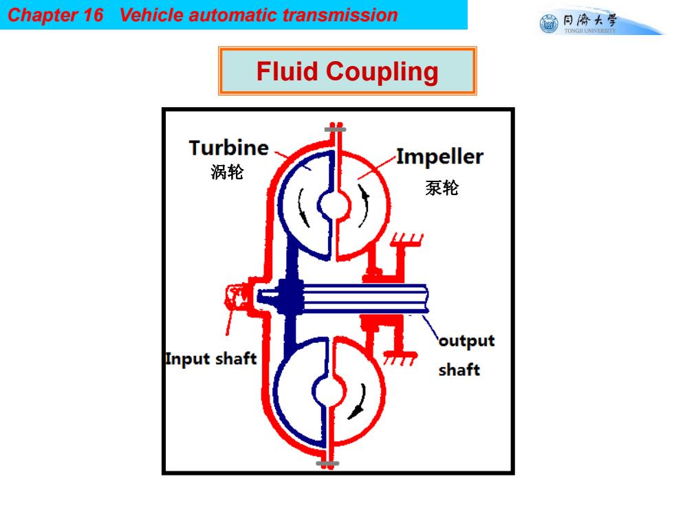
Chapter 16 Vehicle automatic transmission 同©大学 TONGII UNIVERSTTY Fluid Coupling Turbine Impeller 涡轮 泵轮 output Input shaft shaft
Chapter 16 Vehicle automatic transmission Fluid Coupling 涡轮 泵轮
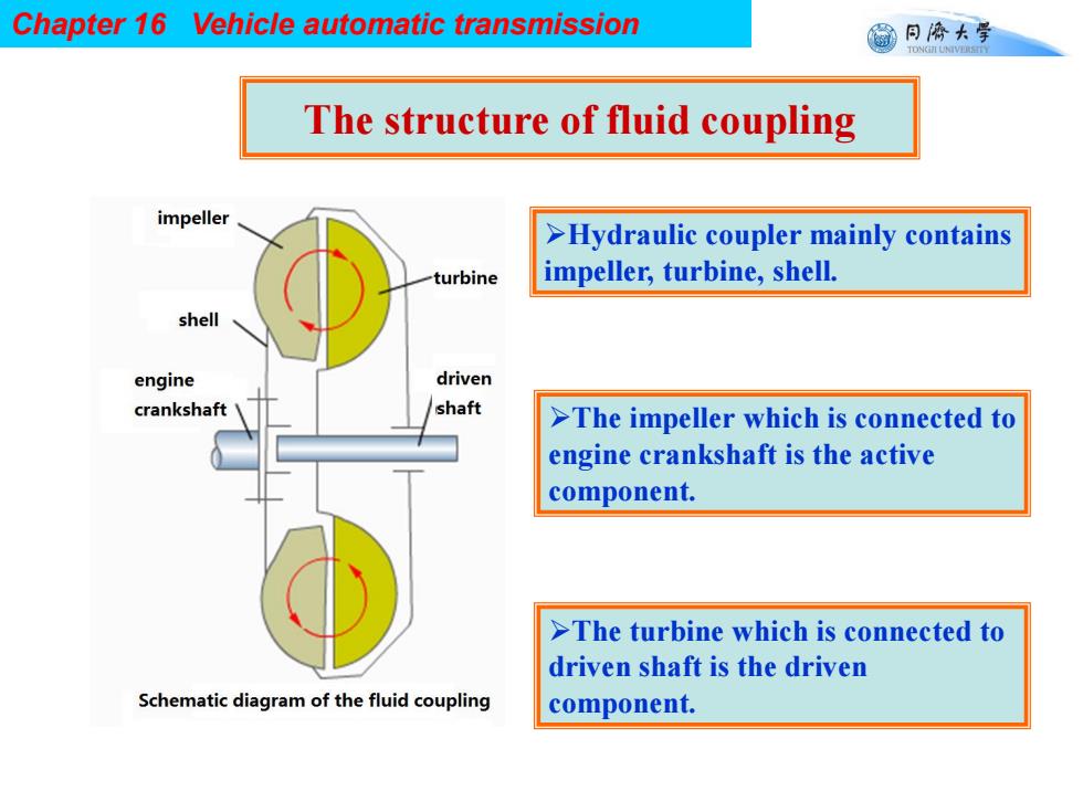
Chapter 16 Vehicle automatic transmission 窗月桥大学 TONGII UNIVERSTTY The structure of fluid coupling impeller >Hydraulic coupler mainly contains turbine impeller,turbine,shell. shell engine driven crankshaft shaft >The impeller which is connected to engine crankshaft is the active component. >The turbine which is connected to driven shaft is the driven Schematic diagram of the fluid coupling component
Chapter 16 Vehicle automatic transmission The structure of fluid coupling Hydraulic coupler mainly contains impeller, turbine, shell. The impeller which is connected to engine crankshaft is the active component. The turbine which is connected to driven shaft is the driven component
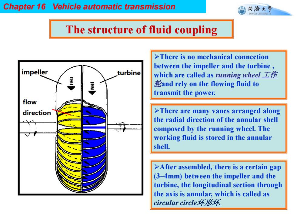
Chapter 16 Vehicle automatic transmission 同©大学 TONGII UNIVERSTTY The structure of fluid coupling >There is no mechanical connection between the impeller and the turbine, impeller turbine which are called as running wheel f and rely on the flowing fluid to transmit the power. flow direction >There are many vanes arranged along the radial direction of the annular shell composed by the running wheel.The working fluid is stored in the annular shell. >After assembled,there is a certain gap (3~4mm)between the impeller and the turbine,the longitudinal section through the axis is annular,which is called as circular circle.环形环
Chapter 16 Vehicle automatic transmission The structure of fluid coupling There is no mechanical connection between the impeller and the turbine , which are called as running wheel 工作 轮and rely on the flowing fluid to transmit the power. There are many vanes arranged along the radial direction of the annular shell composed by the running wheel. The working fluid is stored in the annular shell. After assembled, there is a certain gap (3~4mm) between the impeller and the turbine, the longitudinal section through the axis is annular, which is called as circular circle环形环