JPKIC 结构设计原理 The principle of structure design -Gotmnsl,/h≤3oeonanieioma2otih9is8a2dhorthebngsiaeofthe .sMall lateral deflection,generally do not count the effects of column section failure is due to reach its ultimate strength of materials caused by,known as material damage. 5<30material damage,consider the second-order moment, reduce capacity u larger lateral deflection,the actual load eccentricity increases with load is non-linear increase in the control section of the final component is due to cross-section of material still to reach its ultimate strength and damage is material damage. ●Slender columns h30-unstable failure,avoid Great column slenderness ratio,the pressure reaches the maximum when the eccentricity,the lateral deflection of a sudden 24 surge,this time,bar the maximum carrying capacity is set out in its control plane strength of the material has not yet reached its breaking strength,this Damage type is called unstable failure. Projects generally should not be used slender column
l 0 / h 5 small lateral deflection, u generally do not count the effects of column section failure is due to reach its ultimate strength of materials caused by, known as material damage. 5 l 0 / h 30 u larger lateral deflection, the actual load eccentricity increases with load is non-linear increase in the control section of the final component is due to cross-section of material still to reach its ultimate strength and damage is material damage. Slender columns Great column slenderness ratio, the pressure reaches the maximum when the eccentricity, the lateral deflection of a sudden surge, this time, bar the maximum carrying capacity is set out in its control plane strength of the material has not yet reached its breaking strength, this Damage type is called unstable failure. Projects generally should not be used slender column. u Columns --- material damage, without regard for the long side of the second order moment of the distance h --- material damage, consider the second-order moment, reduce capacity 30 --- unstable failure, avoid l 0 h
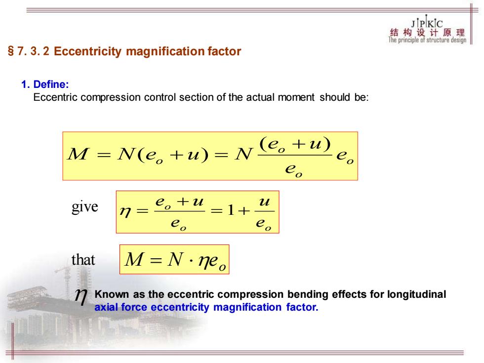
JPKIC 结构设计原理 Tfeprniipledistnctiredesign S 7.3.2 Eccentricity magnification factor 1.Define: Eccentric compression control section of the actual moment should be: M=N(e。+w)=Ne。+u) e eo give 7 e。+u =1+4 eo eo that M=N·eo Known as the eccentric compression bending effects for longitudinal axial force eccentricity magnification factor
§7.3.2 Eccentricity magnification factor 1. Define: Eccentric compression control section of the actual moment should be: o o o o e e e u M N e u N ( ) ( ) + = + = give o o o e u e e u = + + = 1 that o M = N e Known as the eccentric compression bending effects for longitudinal axial force eccentricity magnification factor.
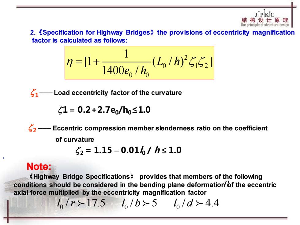
JIPKIC 结构设计原理 The principle of structure design 2.<Specification for Highway Bridges)the provisions of eccentricity magnification factor is calculated as follows: 7=[1+ 1400e/h (L/h)25152] 1-Load eccentricity factor of the curvature 1=0.2+2.7e/ho≤1.0 62-Eccentric compression member slenderness ratio on the coefficient of curvature 52=1.15-0.016/h≤1.0 Note: <Highway Bridge Specifications)provides that members of the following conditions should be considered in the bending plane deformation of the eccentric axial force multiplied by the eccentricity magnification factor /r>17.51/b>5 /d>4.4
2.《Specification for Highway Bridges》the provisions of eccentricity magnification factor is calculated as follows: 2 ––– Eccentric compression member slenderness ratio on the coefficient of curvature 2 = 1.15 – 0.01l0 / h 1.0 1 ––– Load eccentricity factor of the curvature 1=0.2+2.7e0/h0≤1.0 2 0 1 2 0 0 1 [1 ( / ) ] 1400 / L h e h = + Note: 《Highway Bridge Specifications》 provides that members of the following conditions should be considered in the bending plane deformation of the eccentric axial force multiplied by the eccentricity magnification factor l 0 /r 17.5 l 0 /b 5 l 0 / d 4.4 。

JPKIc 结构设计原理 jhepnhepledstucturedesgn S 7.4 Rectangular Eccentric Compression Bearing Capacity Of Normal Section S 7.4.1 Rectangular eccentric compression bearing capacity of the basic formula Basic assumptions are: Plane-section assumption. Do not take into account the tensile strength of concrete in tension. C50及以下时£w=0.0033 Compression zone of concrete ultimate C80时8m=0.003 compressive strain. The picture shows the rectangle of concrete fed'x=Bxo ompressive stress,stress concentration degree
§7.4 Rectangular Eccentric Compression Bearing Capacity Of Normal Section §7.4.1 Rectangular eccentric compression bearing capacity of the basic formula Basic assumptions are: Plane-section assumption. Do not take into account the tensile strength of concrete in tension. Compression zone of concrete ultimate compressive strain. 50 0.0033 80 0.003 cu cu C C = = 及以下时 时 The picture shows the rectangle of concrete ompressive stress, stress concentration degree cd 0 f x x , =
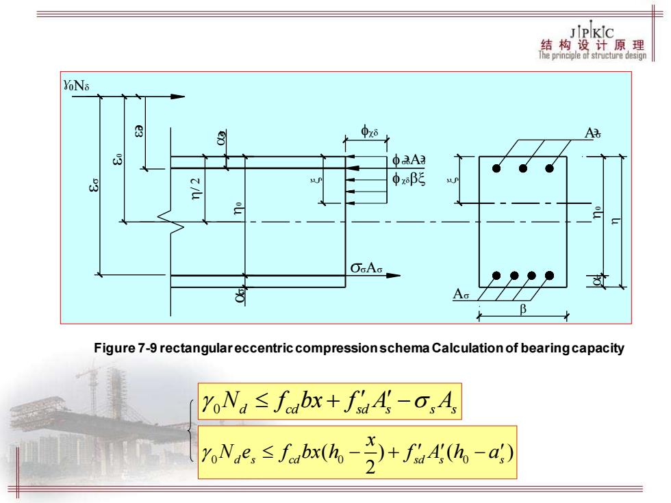
JPKic 结构盘计原课 YoNs 8 018 A 中A2 8 中xβ OGAG Figure 7-9 rectangulareccentric compression schema Calculation of bearing capacity oNa≤fabx+faA-o,A Ne,≤fbxh-+f4-a)
Figure 7-9 rectangular eccentric compression schema Calculation of bearing capacity 0 N f bx f A A d cd sd s s s + − 0 0 0 ( ) ( ) 2 d s cd sd s s x N e f bx h f A h a − + −