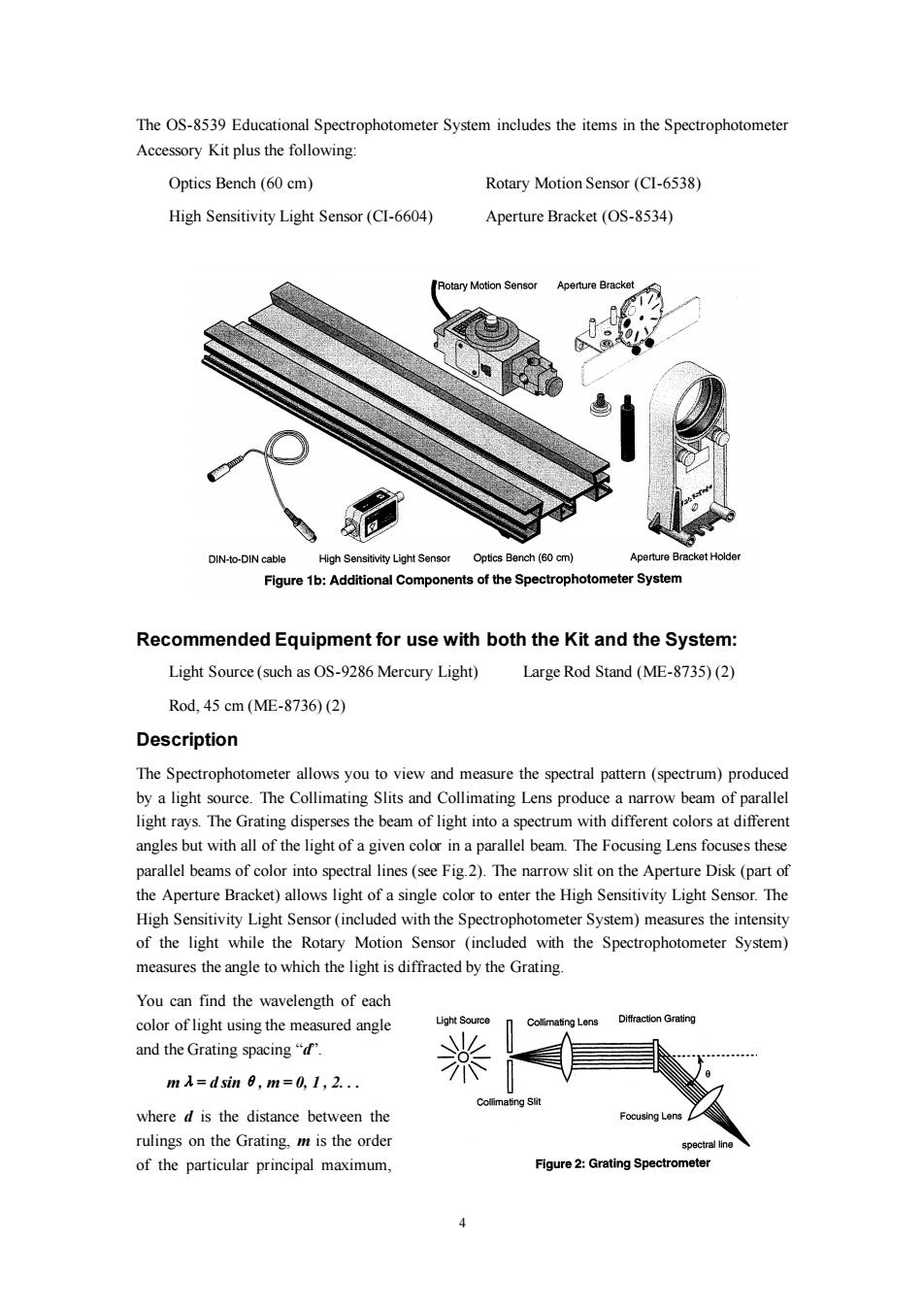
The OS-8539 Educational Spectrophotometer System includes the items in the Spectrophotometer Accessory Kit plus the following: Optics Bench (60 cm) Rotary Motion Sensor(CI-6538) High Sensitivity Light Sensor(CI-6604) Aperture Bracket(OS-8534) Rotary Motion Sensor Aperture Bracket DIN-to-DIN cable High Sensitivity Light Sensor Optics Bench (60 cm) Aperture Bracket Holder Figure 1b:Additional Components of the Spectrophotometer System Recommended Equipment for use with both the Kit and the System: Light Source(such as OS-9286 Mercury Light) Large Rod Stand(ME-8735)(2) Rod,45cm(ME-8736)(2) Description The Spectrophotometer allows you to view and measure the spectral pattern(spectrum)produced by a light source.The Collimating Slits and Collimating Lens produce a narrow beam of parallel light rays.The Grating disperses the beam of light into a spectrum with different colors at different angles but with all of the light of a given color in a parallel beam.The Focusing Lens focuses these parallel beams of color into spectral lines(see Fig.2).The narrow slit on the Aperture Disk(part of the Aperture Bracket)allows light of a single color to enter the High Sensitivity Light Sensor.The High Sensitivity Light Sensor(included with the Spectrophotometer System)measures the intensity of the light while the Rotary Motion Sensor (included with the Spectrophotometer System) measures the angle to which the light is diffracted by the Grating. You can find the wavelength of each color of light using the measured angle Light Source mating Lens Diffraction Grating and the Grating spacing"d. 米 mA=dsin8,m=0,1,2.. Collimating Slit where d is the distance between the Focusing Lens rulings on the Grating,m is the order spectral line of the particular principal maximum, Figure 2:Grating Spectrometer
4 The OS-8539 Educational Spectrophotometer System includes the items in the Spectrophotometer Accessory Kit plus the following: Optics Bench (60 cm) Rotary Motion Sensor (CI-6538) High Sensitivity Light Sensor (CI-6604) Aperture Bracket (OS-8534) Recommended Equipment for use with both the Kit and the System: Light Source (such as OS-9286 Mercury Light) Large Rod Stand (ME-8735) (2) Rod, 45 cm (ME-8736) (2) Description The Spectrophotometer allows you to view and measure the spectral pattern (spectrum) produced by a light source. The Collimating Slits and Collimating Lens produce a narrow beam of parallel light rays. The Grating disperses the beam of light into a spectrum with different colors at different angles but with all of the light of a given color in a parallel beam. The Focusing Lens focuses these parallel beams of color into spectral lines (see Fig.2). The narrow slit on the Aperture Disk (part of the Aperture Bracket) allows light of a single color to enter the High Sensitivity Light Sensor. The High Sensitivity Light Sensor (included with the Spectrophotometer System) measures the intensity of the light while the Rotary Motion Sensor (included with the Spectrophotometer System) measures the angle to which the light is diffracted by the Grating. You can find the wavelength of each color of light using the measured angle and the Grating spacing “d”. mλ= d sinθ, m = 0, 1 , 2. . . where d is the distance between the rulings on the Grating, m is the order of the particular principal maximum
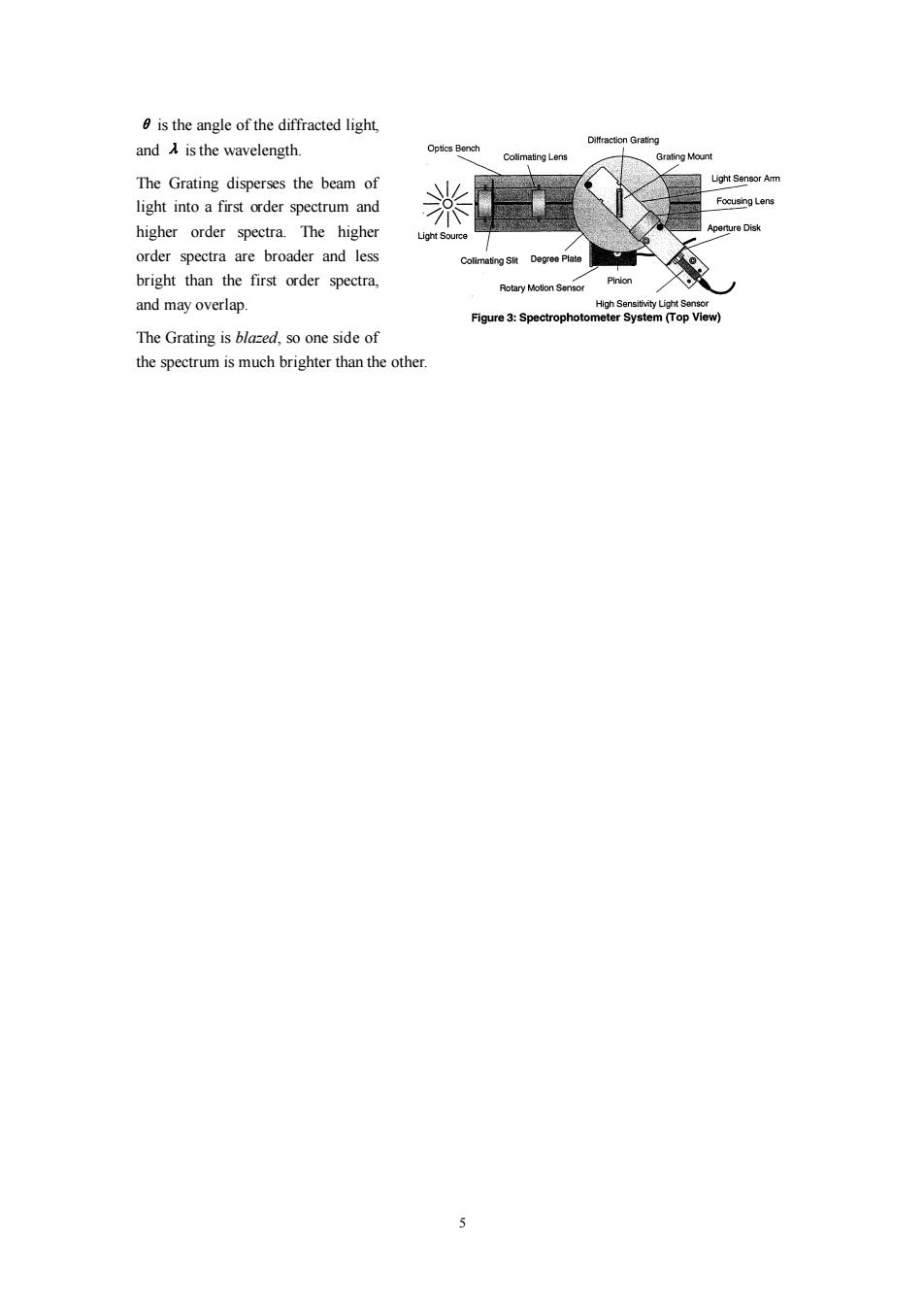
is the angle of the diffracted light, and is the wavelength Ditfraction Grating Optics Bench Collimating Lens Grating Mount The Grating disperses the beam of Light Sensor Amm light into a first order spectrum and 米 Focusing Lens higher order spectra.The higher Light Source Aperture Disk order spectra are broader and less Colimating Slit Degree Plate bright than the first order spectra, Pinion Rotary Motion Sensor and may overlap. High Sensitivity Light Sensor Figure 3:Spectrophotometer System (Top View) The Grating is blazed,so one side of the spectrum is much brighter than the other 5
5 θ is the angle of the diffracted light, and λ is the wavelength. The Grating disperses the beam of light into a first order spectrum and higher order spectra. The higher order spectra are broader and less bright than the first order spectra, and may overlap. The Grating is blazed, so one side of the spectrum is much brighter than the other
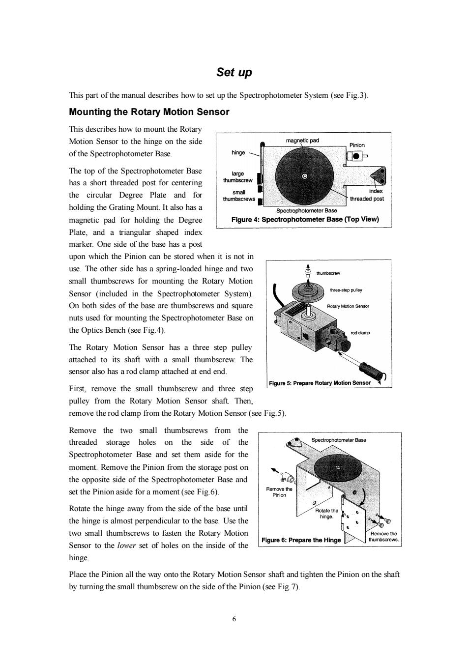
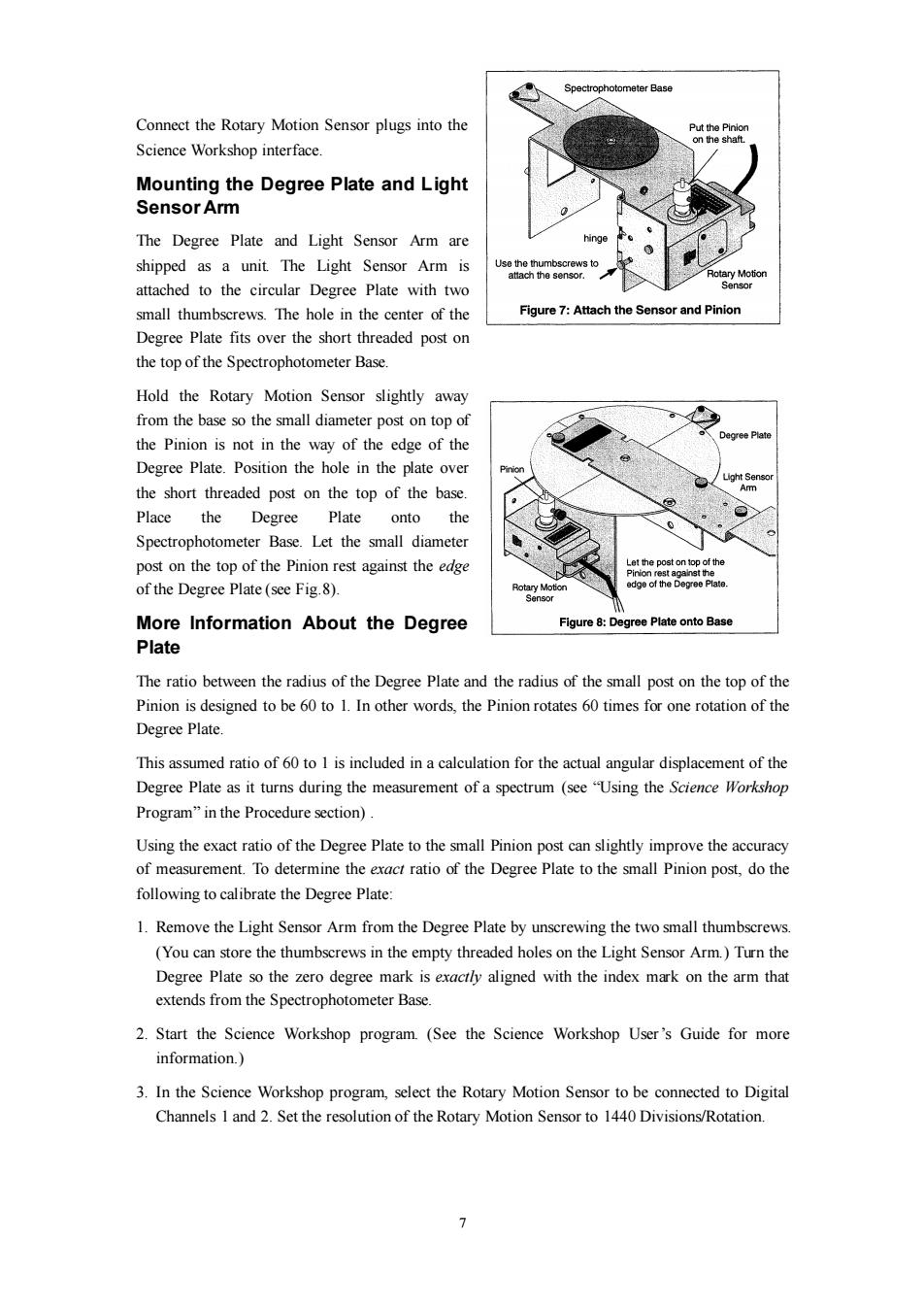
Set up This part of the manual describes how to set up the Spectrophotometer System (see Fig.3). Mounting the Rotary Motion Sensor This describes how to mount the Rotary Motion Sensor to the hinge on the side magnetic pad Pinion of the Spectrophotometer Base. hinge The top of the Spectrophotometer Base large has a short threaded post for centering thumbscrew the circular Degree Plate and for small index thumbscrews threaded post holding the Grating Mount.It also has a Spectrophotometer Base magnetic pad for holding the Degree Figure 4:Spectrophotometer Base (Top View) Plate,and a triangular shaped index marker.One side of the base has a post upon which the Pinion can be stored when it is not in use.The other side has a spring-loaded hinge and two thumbscrew small thumbscrews for mounting the Rotary Motion Sensor (included in the Spectrophotometer System). three-step pulley On both sides of the base are thumbscrews and square Rotary Motion Sensor nuts used for mounting the Spectrophotometer Base on the Optics Bench(see Fig.4). rod cle m The Rotary Motion Sensor has a three step pulley attached to its shaft with a small thumbscrew.The sensor also has a rod clamp attached at end end. Figure 5:Prepare Rotary Motion Sensor First,remove the small thumbscrew and three step pulley from the Rotary Motion Sensor shaft.Then remove the rod clamp from the Rotary Motion Sensor(see Fig.5). Remove the two small thumbscrews from the threaded storage holes on the side of the Spectrophotometer Base Spectrophotometer Base and set them aside for the moment.Remove the Pinion from the storage post on the opposite side of the Spectrophotometer Base and set the Pinion aside for a moment(see Fig.6). Remove the Pinion 0 Rotate the hinge away from the side of the base until Rotate the the hinge is almost perpendicular to the base.Use the hinge. two small thumbscrews to fasten the Rotary Motion Figure 6:Prepare the Hinge Sensor to the lower set of holes on the inside of the hinge Place the Pinion all the way onto the Rotary Motion Sensor shaft and tighten the Pinion on the shaft by turning the small thumbscrew on the side of the Pinion(see Fig.7). 6
6 Set up This part of the manual describes how to set up the Spectrophotometer System (see Fig.3). Mounting the Rotary Motion Sensor This describes how to mount the Rotary Motion Sensor to the hinge on the side of the Spectrophotometer Base. The top of the Spectrophotometer Base has a short threaded post for centering the circular Degree Plate and for holding the Grating Mount. It also has a magnetic pad for holding the Degree Plate, and a triangular shaped index marker. One side of the base has a post upon which the Pinion can be stored when it is not in use. The other side has a spring-loaded hinge and two small thumbscrews for mounting the Rotary Motion Sensor (included in the Spectrophotometer System). On both sides of the base are thumbscrews and square nuts used for mounting the Spectrophotometer Base on the Optics Bench (see Fig.4). The Rotary Motion Sensor has a three step pulley attached to its shaft with a small thumbscrew. The sensor also has a rod clamp attached at end end. First, remove the small thumbscrew and three step pulley from the Rotary Motion Sensor shaft. Then, remove the rod clamp from the Rotary Motion Sensor (see Fig.5). Remove the two small thumbscrews from the threaded storage holes on the side of the Spectrophotometer Base and set them aside for the moment. Remove the Pinion from the storage post on the opposite side of the Spectrophotometer Base and set the Pinion aside for a moment (see Fig.6). Rotate the hinge away from the side of the base until the hinge is almost perpendicular to the base. Use the two small thumbscrews to fasten the Rotary Motion Sensor to the lower set of holes on the inside of the hinge. Place the Pinion all the way onto the Rotary Motion Sensor shaft and tighten the Pinion on the shaft by turning the small thumbscrew on the side of the Pinion (see Fig.7)
Spectrophotometer Base Connect the Rotary Motion Sensor plugs into the Put the Pinion Science Workshop interface. on the shaft. Mounting the Degree Plate and Light Sensor Arm The Degree Plate and Light Sensor Arm are shipped as a unit.The Light Sensor Arm is Use the thumbscrew attach the senso Rotary Motion attached to the circular Degree Plate with two Sensor small thumbscrews.The hole in the center of the Figure 7:Attach the Sensor and Pinion Degree Plate fits over the short threaded post on the top of the Spectrophotometer Base. Hold the Rotary Motion Sensor slightly away from the base so the small diameter post on top of the Pinion is not in the way of the edge of the Degree Plate Degree Plate.Position the hole in the plate over the short threaded post on the top of the base. m Place the Degree Plate onto the Spectrophotometer Base.Let the small diameter post on the top of the Pinion rest against the edge Let the post on top of the Pinion rest against the of the Degree Plate (see Fig.8). edge of the Degree Plate. More Information About the Degree Figure 8:Degree Plate onto Base Plate The ratio between the radius of the Degree Plate and the radius of the small post on the top of the Pinion is designed to be 60 to 1.In other words,the Pinion rotates 60 times for one rotation of the Degree Plate. This assumed ratio of 60 to 1 is included in a calculation for the actual angular displacement of the Degree Plate as it turns during the measurement of a spectrum (see"Using the Science Workshop Program"in the Procedure section). Using the exact ratio of the Degree Plate to the small Pinion post can slightly improve the accuracy of measurement.To determine the exact ratio of the Degree Plate to the small Pinion post,do the following to calibrate the Degree Plate: 1.Remove the Light Sensor Arm from the Degree Plate by unscrewing the two small thumbscrews. (You can store the thumbscrews in the empty threaded holes on the Light Sensor Arm.)Turn the Degree Plate so the zero degree mark is exactly aligned with the index mark on the arm that extends from the Spectrophotometer Base. 2.Start the Science Workshop program.(See the Science Workshop User's Guide for more information.) 3.In the Science Workshop program,select the Rotary Motion Sensor to be connected to Digital Channels 1 and 2.Set the resolution of the Rotary Motion Sensor to 1440 Divisions/Rotation. >
7 Connect the Rotary Motion Sensor plugs into the Science Workshop interface. Mounting the Degree Plate and Light Sensor Arm The Degree Plate and Light Sensor Arm are shipped as a unit. The Light Sensor Arm is attached to the circular Degree Plate with two small thumbscrews. The hole in the center of the Degree Plate fits over the short threaded post on the top of the Spectrophotometer Base. Hold the Rotary Motion Sensor slightly away from the base so the small diameter post on top of the Pinion is not in the way of the edge of the Degree Plate. Position the hole in the plate over the short threaded post on the top of the base. Place the Degree Plate onto the Spectrophotometer Base. Let the small diameter post on the top of the Pinion rest against the edge of the Degree Plate (see Fig.8). More Information About the Degree Plate The ratio between the radius of the Degree Plate and the radius of the small post on the top of the Pinion is designed to be 60 to 1. In other words, the Pinion rotates 60 times for one rotation of the Degree Plate. This assumed ratio of 60 to 1 is included in a calculation for the actual angular displacement of the Degree Plate as it turns during the measurement of a spectrum (see “Using the Science Workshop Program” in the Procedure section) . Using the exact ratio of the Degree Plate to the small Pinion post can slightly improve the accuracy of measurement. To determine the exact ratio of the Degree Plate to the small Pinion post, do the following to calibrate the Degree Plate: 1. Remove the Light Sensor Arm from the Degree Plate by unscrewing the two small thumbscrews. (You can store the thumbscrews in the empty threaded holes on the Light Sensor Arm.) Turn the Degree Plate so the zero degree mark is exactly aligned with the index mark on the arm that extends from the Spectrophotometer Base. 2. Start the Science Workshop program. (See the Science Workshop User’s Guide for more information.) 3. In the Science Workshop program, select the Rotary Motion Sensor to be connected to Digital Channels 1 and 2. Set the resolution of the Rotary Motion Sensor to 1440 Divisions/Rotation
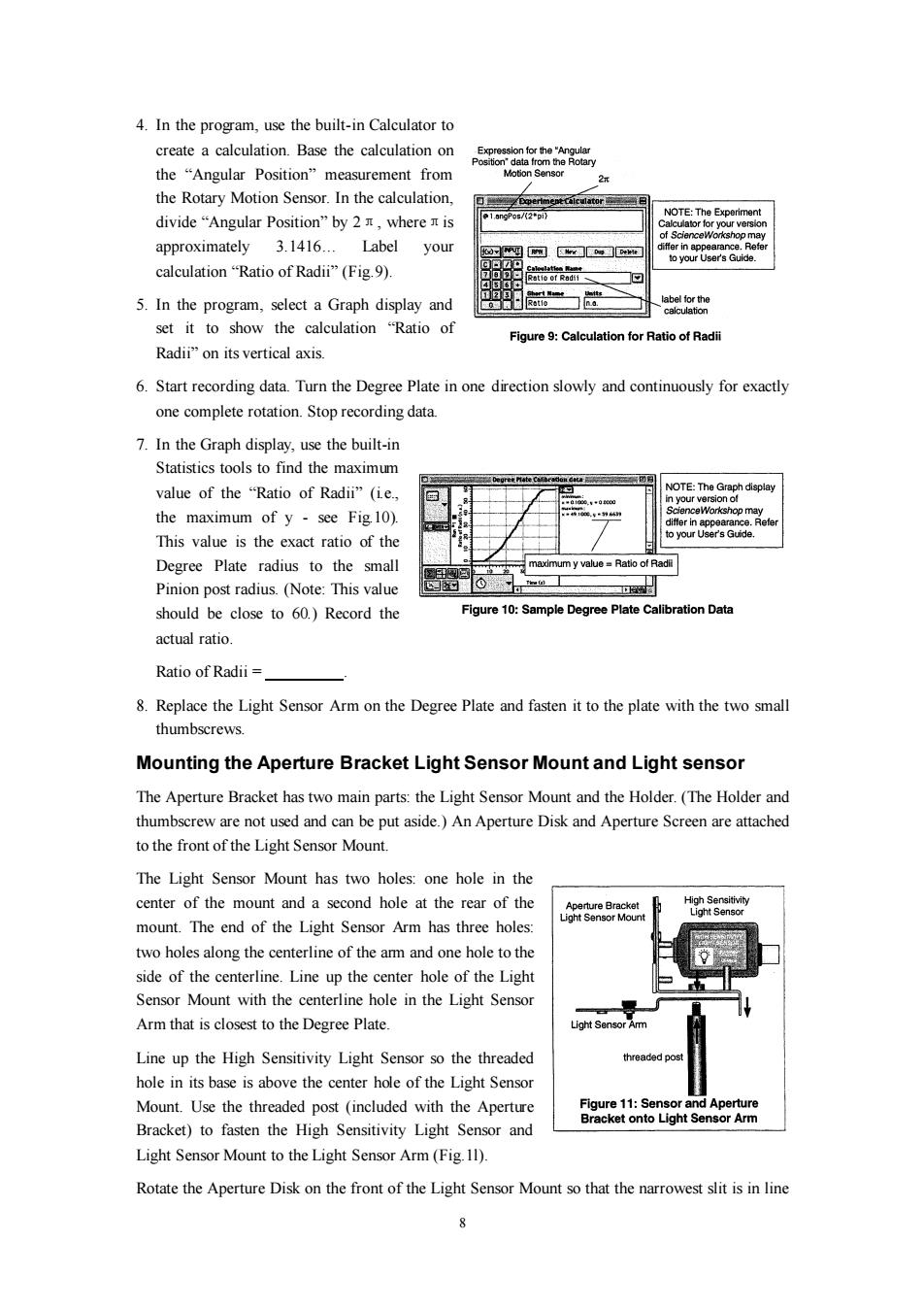
4.In the program,use the built-in Calculator to create a calculation.Base the calculation on the“Angular Position”measurement from Votion Senso the Rotary Motion Sensor.In the calculation, 1.angPos/(2pi) NOTE:The Experiment divide“Angular Position'”by2T,where is Calculator for your version of ScienceWorkshop may approximately 3.1416...Label your differ in appearance.Refer to your User's Guide. calculation“Ratio of Radii”(Fig.9). tatio of Radii 5.In the program,select a Graph display and label for the calculation set it to show the calculation "Ratio of Figure 9:Calculation for Ratio of Radii Radii"on its vertical axis. 6.Start recording data.Turn the Degree Plate in one direction slowly and continuously for exactly one complete rotation.Stop recording data. 7.In the Graph display,use the built-in Statistics tools to find the maximum value of the "Ratio of Radii"(ie., NOTE:The Graph dispiay ersion of the maximum of y-see Fig.10). iffer in appearance.Refe This value is the exact ratio of the your User's Guide. Degree Plate radius to the small maximum y value=Ratio of Radi Pinion post radius.(Note:This value 工 should be close to 60.)Record the Figure 10:Sample Degree Plate Calibration Data actual ratio Ratio of Radii 8.Replace the Light Sensor Arm on the Degree Plate and fasten it to the plate with the two small thumbscrews. Mounting the Aperture Bracket Light Sensor Mount and Light sensor The Aperture Bracket has two main parts:the Light Sensor Mount and the Holder.(The Holder and thumbscrew are not used and can be put aside.)An Aperture Disk and Aperture Screen are attached to the front of the Light Sensor Mount. The Light Sensor Mount has two holes:one hole in the center of the mount and a second hole at the rear of the Aperture Bracket High Sensitivity Light Sensor Mount Light Sensor mount.The end of the Light Sensor Arm has three holes: two holes along the centerline of the am and one hole to the side of the centerline.Line up the center hole of the Light Sensor Mount with the centerline hole in the Light Sensor Arm that is closest to the Degree Plate. Light Sensor Arm Line up the High Sensitivity Light Sensor so the threaded threaded post hole in its base is above the center hole of the Light Sensor Mount.Use the threaded post (included with the Aperture Figure 11:Sensor and Aperture Bracket onto Light Sensor Arm Bracket)to fasten the High Sensitivity Light Sensor and Light Sensor Mount to the Light Sensor Arm(Fig.11). Rotate the Aperture Disk on the front of the Light Sensor Mount so that the narrowest slit is in line
8 4. In the program, use the built-in Calculator to create a calculation. Base the calculation on the “Angular Position” measurement from the Rotary Motion Sensor. In the calculation, divide “Angular Position” by 2π, whereπis approximately 3.1416… Label your calculation “Ratio of Radii” (Fig.9). 5. In the program, select a Graph display and set it to show the calculation “Ratio of Radii” on its vertical axis. 6. Start recording data. Turn the Degree Plate in one direction slowly and continuously for exactly one complete rotation. Stop recording data. 7. In the Graph display, use the built-in Statistics tools to find the maximum value of the “Ratio of Radii” (i.e., the maximum of y - see Fig.10). This value is the exact ratio of the Degree Plate radius to the small Pinion post radius. (Note: This value should be close to 60.) Record the actual ratio. Ratio of Radii = . 8. Replace the Light Sensor Arm on the Degree Plate and fasten it to the plate with the two small thumbscrews. Mounting the Aperture Bracket Light Sensor Mount and Light sensor The Aperture Bracket has two main parts: the Light Sensor Mount and the Holder. (The Holder and thumbscrew are not used and can be put aside.) An Aperture Disk and Aperture Screen are attached to the front of the Light Sensor Mount. The Light Sensor Mount has two holes: one hole in the center of the mount and a second hole at the rear of the mount. The end of the Light Sensor Arm has three holes: two holes along the centerline of the arm and one hole to the side of the centerline. Line up the center hole of the Light Sensor Mount with the centerline hole in the Light Sensor Arm that is closest to the Degree Plate. Line up the High Sensitivity Light Sensor so the threaded hole in its base is above the center hole of the Light Sensor Mount. Use the threaded post (included with the Aperture Bracket) to fasten the High Sensitivity Light Sensor and Light Sensor Mount to the Light Sensor Arm (Fig.1l). Rotate the Aperture Disk on the front of the Light Sensor Mount so that the narrowest slit is in line