coolants that can then be used to drive a turbine cycle and generator to produce electricity,or for static systems,a thermoelectric or thermionic conversion to electricity. Electric propulsion can be used over a wide range of missions including GEO station keeping and orbital plane changes,orbital transfer (LEO to GEO),and interplanetary travel.Different electric propulsion devices can be used depending on the mission requirements.Electric propulsion devices create significantly higher exhaust velocities in the range of 40-90 km/sec versus around 4-5 km/sec for chemical systems. Exhaust velocities directly relate to specific impulse,a measure of propulsion efficiency, by the equation: c=gIsp (2) Where c is exhaust velocity,g is the acceleration of gravity on the Earth's surface and Isp is specific impulse.Specific impulse is defined as the amount of total impulse obtained for the weight(in 1g)of fuel expended.The high exhaust velocities allow for a reduction in required propellant mass as illustrated in Equation 3 or in an alternate expression that is commonly known as the Rocket Equation,Equation 4. Mi/Mo=e"(AVIe) (3) △V=Isp*g*ln(M/Mf) (4) Here Mr is the final spacecraft mass,Mo is the initial spacecraft mass (including propellant)and AV is the achievable velocity increment. Due to power limitations,electric propulsion systems produce low thrust,and in order to create enough velocity,operate through most of the mission profile.Mission profiles that utilize electric propulsion may also include a deceleration phase of the 22
coolants that can then be used to drive a turbine cycle and generator to produce electricity, or for static systems, a thermoelectric or thermionic conversion to electricity. Electric propulsion can be used over a wide range of missions including GEO station keeping and orbital plane changes, orbital transfer (LEO to GEO), and interplanetary travel. Different electric propulsion devices can be used depending on the mission requirements. Electric propulsion devices create significantly higher exhaust velocities in the range of 40-90 km/sec versus around 4-5 km/sec for chemical systems. Exhaust velocities directly relate to specific impulse, a measure of propulsion efficiency, by the equation: c = g Isp (2) Where c is exhaust velocity, g is the acceleration of gravity on the Earth’s surface and Isp is specific impulse. Specific impulse is defined as the amount of total impulse obtained for the weight (in 1g) of fuel expended. The high exhaust velocities allow for a reduction in required propellant mass as illustrated in Equation 3 or in an alternate expression that is commonly known as the Rocket Equation, Equation 4. Mf/Mo = e- (∆V/ c) (3) ∆V = Isp * g * ln (Mo / Mf) (4) Here Mf is the final spacecraft mass, Mo is the initial spacecraft mass (including propellant) and ∆V is the achievable velocity increment. Due to power limitations, electric propulsion systems produce low thrust, and in order to create enough velocity, operate through most of the mission profile. Mission profiles that utilize electric propulsion may also include a deceleration phase of the 22
mission that can enable orbital capture or,given sufficient energy and propellant, multiple orbits and exits of planetary,moon or asteroid systems. For Earth escape or orbit raising missions (e.g.LEO to GEO orbit transfer),or high planetary gravity environments,a spiral trajectory is used to overcome the higher localized gravity and compensate for the low acceleration.Consequently for Earth orbital missions,while propellant requirements and system mass and launch vehicle requirements decrease,trip times will increase. Differences in trip times,as compared to chemical missions,will eventually decrease as distances increase and NEPP vehicles can follow a more direct trajectory without the use of time consuming planetary gravity assists.Additionally,having the ability to use direct planetary trajectories allows for less restrictive launch windows that decouples the launch date from limited planetary alignments. Electric propulsion systems require high power levels to generate acceleration or thrust.Theoretically,power levels can range from 10's of kilowatts to 10's of megawatts for an NEPP system.The benefits of electric propulsion increase as the mass of the propulsion system or specific mass,as expressed as the ratio of propulsion system mass to power delivered,decreases.Introducing nuclear power significantly increases power densities and lowers the specific mass of electric propulsion systems for planetary applications.In summary the benefits are:(1)The ability to reach interplanetary destinations in a propellant efficient manner which allows for more science payload over propellant loading for a given launch vehicle,(2)The ability to uncouple complex mission designs using planetary gravity assists due to the direct trajectories capability,(3) Potentially decreasing trip time to planetary destinations(4)Having high power levels at 23
mission that can enable orbital capture or, given sufficient energy and propellant, multiple orbits and exits of planetary, moon or asteroid systems. For Earth escape or orbit raising missions (e.g. LEO to GEO orbit transfer), or high planetary gravity environments, a spiral trajectory is used to overcome the higher localized gravity and compensate for the low acceleration. Consequently for Earth orbital missions, while propellant requirements and system mass and launch vehicle requirements decrease, trip times will increase. Differences in trip times, as compared to chemical missions, will eventually decrease as distances increase and NEPP vehicles can follow a more direct trajectory without the use of time consuming planetary gravity assists. Additionally, having the ability to use direct planetary trajectories allows for less restrictive launch windows that decouples the launch date from limited planetary alignments. Electric propulsion systems require high power levels to generate acceleration or thrust. Theoretically, power levels can range from 10’s of kilowatts to 10’s of megawatts for an NEPP system. The benefits of electric propulsion increase as the mass of the propulsion system or specific mass, as expressed as the ratio of propulsion system mass to power delivered, decreases. Introducing nuclear power significantly increases power densities and lowers the specific mass of electric propulsion systems for planetary applications. In summary the benefits are: (1) The ability to reach interplanetary destinations in a propellant efficient manner which allows for more science payload over propellant loading for a given launch vehicle, (2) The ability to uncouple complex mission designs using planetary gravity assists due to the direct trajectories capability, (3) Potentially decreasing trip time to planetary destinations (4) Having high power levels at 23
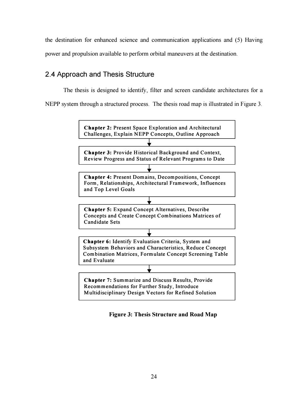
the destination for enhanced science and communication applications and(5)Having power and propulsion available to perform orbital maneuvers at the destination. 2.4 Approach and Thesis Structure The thesis is designed to identify,filter and screen candidate architectures for a NEPP system through a structured process.The thesis road map is illustrated in Figure 3. Chapter 2:Present Space Exploration and Architectural Challenges,Explain NEPP Concepts,Outline Approach Chapter 3:Provide Historical Background and Context, Review Progress and Status of Relevant Programs to Date Chapter 4:Present Domains,Decompositions,Concept Form,Relationships,Architectural Framework,Influences and Top Level Goals Chapter 5:Expand Concept Alternatives,Describe Concepts and Create Concept Combinations Matrices of Candidate Sets Chapter 6:Identify Evaluation Criteria,System and Subsystem Behaviors and Characteristics,Reduce Concept Combination Matrices,Formulate Concept Screening Table and Evaluate Chapter 7:Summarize and Discuss Results,Provide Recommendations for Further Study,Introduce Multidisciplinary Design Vectors for Refined Solution Figure 3:Thesis Structure and Road Map 24
the destination for enhanced science and communication applications and (5) Having power and propulsion available to perform orbital maneuvers at the destination. 2.4 Approach and Thesis Structure The thesis is designed to identify, filter and screen candidate architectures for a NEPP system through a structured process. The thesis road map is illustrated in Figure 3. Chapter 3: Provide Historical Background and Context, Review Progress and Status of Relevant Programs to Date Chapter 4: Present Domains, Decompositions, Concept Form, Relationships, Architectural Framework, Influences and Top Level Goals Chapter 6: Identify Evaluation Criteria, System and Subsystem Behaviors and Characteristics, Reduce Concept Combination Matrices, Formulate Concept Screening Table and Evaluate Chapter 5: Expand Concept Alternatives, Describe Concepts and Create Concept Combinations Matrices of Candidate Sets Chapter 7: Summarize and Discuss Results, Provide Recommendations for Further Study, Introduce Multidisciplinary Design Vectors for Refined Solution Chapter 2: Present Space Exploration and Architectural Challenges, Explain NEPP Concepts, Outline Approach Chapter 3: Provide Historical Background and Context, Review Progress and Status of Relevant Programs to Date Chapter 4: Present Domains, Decompositions, Concept Form, Relationships, Architectural Framework, Influences and Top Level Goals Chapter 6: Identify Evaluation Criteria, System and Subsystem Behaviors and Characteristics, Reduce Concept Combination Matrices, Formulate Concept Screening Table and Evaluate Chapter 5: Expand Concept Alternatives, Describe Concepts and Create Concept Combinations Matrices of Candidate Sets Chapter 7: Summarize and Discuss Results, Provide Recommendations for Further Study, Introduce Multidisciplinary Design Vectors for Refined Solution Chapter 2: Present Space Exploration and Architectural Challenges, Explain NEPP Concepts, Outline Approach Figure 3: Thesis Structure and Road Map 24
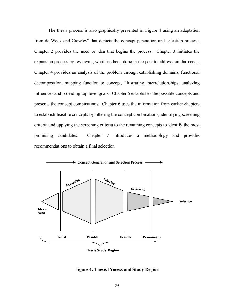
The thesis process is also graphically presented in Figure 4 using an adaptation from de Weck and Crawley*that depicts the concept generation and selection process. Chapter 2 provides the need or idea that begins the process.Chapter 3 initiates the expansion process by reviewing what has been done in the past to address similar needs Chapter 4 provides an analysis of the problem through establishing domains,functional decomposition,mapping function to concept,illustrating interrelationships,analyzing influences and providing top level goals.Chapter 5 establishes the possible concepts and presents the concept combinations.Chapter 6 uses the information from earlier chapters to establish feasible concepts by filtering the concept combinations,identifying screening criteria and applying the screening criteria to the remaining concepts to identify the most promising candidates. Chapter 7 introduces a methodology and provides recommendations to obtain a final selection. +Concept Generation and Selection Process Expansio雅 Filtering Screening Selection Idea or Need Initial Possible Feasible Promising Thesis Study Region Figure 4:Thesis Process and Study Region 25
The thesis process is also graphically presented in Figure 4 using an adaptation from de Weck and Crawley4 that depicts the concept generation and selection process. Chapter 2 provides the need or idea that begins the process. Chapter 3 initiates the expansion process by reviewing what has been done in the past to address similar needs. Chapter 4 provides an analysis of the problem through establishing domains, functional decomposition, mapping function to concept, illustrating interrelationships, analyzing influences and providing top level goals. Chapter 5 establishes the possible concepts and presents the concept combinations. Chapter 6 uses the information from earlier chapters to establish feasible concepts by filtering the concept combinations, identifying screening criteria and applying the screening criteria to the remaining concepts to identify the most promising candidates. Chapter 7 introduces a methodology and provides recommendations to obtain a final selection. Selection Initial Possible Feasible Promising Idea or Need Thesis Study Region Concept Generation and Selection Process Expansion Filtering Screening Selection Initial Possible Feasible Promising Idea or Need Thesis Study Region Concept Generation and Selection Process Expansion Filtering Screening Figure 4: Thesis Process and Study Region 25
3.0 Review of Progress in Nuclear Electric Propulsion 3.1 Historical Context of Nuclear Space Systems The history of nuclear propulsion can be traced to the writings of Dr.Robert Goddard and others prior to Word War II where the concept of heating a working fluid to high temperature using fission for use as a rocket propellant was introduced.>After World War II interest increased in developing nuclear weapons that could be delivered via a ballistic trajectory over intercontinental distances.Because chemical rockets were limited in payload and range,nuclear rockets were pursued within the official nuclear rocket program,code-named Project Rover,beginning in 1955.The Rover/NERVA (Nuclear Engine for Rocket Vehicle Applications)program involved government laboratories,university and industry partners,and resulted in the development of several reactors and ground experimental engines.Project Rover ended in 1973 parallel with the ending of the Apollo program as future space missions were unclear and chemical rocketry had made significant advancements in both range and payload capability for military and civilian purposes. Concurrently the study of small nuclear reactors for satellite use began,and in 1951 the Air Force had arranged for the Atomic Energy Commission to begin work on small reactors suitable for use as power sources in satellite vehicles.7 By 1953 Air Force headquarters directed the research and development command to investigate the feasibility of starting development work on an auxiliary nuclear power plant for a satellite.8 The various earlier efforts and projects eventually became the Space Nuclear Auxiliary Power (SNAP)Program which in 1961 successfully orbited the Transit 4A spacecraft with a SNAP-3B,2.7 W Radioisotope Thermoelectric Generator(RTG). 26
3.0 Review of Progress in Nuclear Electric Propulsion 3.1 Historical Context of Nuclear Space Systems The history of nuclear propulsion can be traced to the writings of Dr. Robert Goddard and others prior to Word War II where the concept of heating a working fluid to high temperature using fission for use as a rocket propellant was introduced.5 After World War II interest increased in developing nuclear weapons that could be delivered via a ballistic trajectory over intercontinental distances. Because chemical rockets were limited in payload and range, nuclear rockets were pursued within the official nuclear rocket program, code-named Project Rover, beginning in 1955.6 The Rover/ NERVA (Nuclear Engine for Rocket Vehicle Applications) program involved government laboratories, university and industry partners, and resulted in the development of several reactors and ground experimental engines. Project Rover ended in 1973 parallel with the ending of the Apollo program as future space missions were unclear and chemical rocketry had made significant advancements in both range and payload capability for military and civilian purposes. Concurrently the study of small nuclear reactors for satellite use began, and in 1951 the Air Force had arranged for the Atomic Energy Commission to begin work on small reactors suitable for use as power sources in satellite vehicles. 7 By 1953 Air Force headquarters directed the research and development command to investigate the feasibility of starting development work on an auxiliary nuclear power plant for a satellite. 8 The various earlier efforts and projects eventually became the Space Nuclear Auxiliary Power (SNAP) Program which in 1961 successfully orbited the Transit 4A spacecraft with a SNAP-3B, 2.7 W Radioisotope Thermoelectric Generator (RTG). 9 26