《画法几何与工程制图》教学大纲 Syllabus of Descriptive Geometry and Engineering Drawing 课程基本信息 Course Information 画法几何与工程制图 课程名称 Course Name Descriptive Geometry and Engineering Drawing 机电工程学院 开课院部 School of Mechanical and 院部代码 04 School Electronics School Code 负责人 Leader 刘衍聪 课程团队 Team Members 工程图学课程组 课程编码 04343 学分 6 Course Code Credits 理论学时 实验学时 0 Lecture Hours 号 Experiment Hours 课内学时 Course Hours 96 上机学时 Programming 0 实践学时 0 Practice Hours Hours 课外学时 Home Hours 适用专业 过程装备与控虹程环境工程5设备机造及基自动化。,车辆工程,机 授课语言 中文 Language of Instruction 先修课程 Prerequisite 无 本课程是一门既有系统理论又有较强实践性的技术基础课程,主要研究用 投影法绘制和阅读工程图样的原理和方法,包括点线面体的投影,图样表达方 法,标准件与常用件,零件图与装配图的绘制,技术要求,绘图国家标准等内 容。使学生具有绘制和阅读工程图样的基本能力,熟悉工程图样的国家标准, 培养学生的绘图技能和空间想象能力,为学习后续课程、完成课程设计与毕业 设计等教学环节打下基础。 课程简介 Thiscourse is both a system theory and technology foundation course with Course Description strong practice.it mainly researches drawing projection method and drawing principle of point,line,plane,solid etc.The expre dhaNiesnadpasadCo assembly drawing.technical requirements,the national standard are also included. The main purpose isto made students grasp the basic ability of drawing and reading of engineering drawings.familiar with national standards of engineering drawing. training students drawing ability and space imagination ability.This a foundation nd aduation desi gn teaching 课程教学大纲
《画法几何与工程制图》教学大纲 Syllabus of Descriptive Geometry and Engineering Drawing 课程基本信息 Course Information 课程名称 Course Name 画法几何与工程制图 Descriptive Geometry and Engineering Drawing 开课院部 School 机电工程学院 School of Mechanical and Electronics 院部代码 School Code 04 负责人 Leader 刘衍聪 课程团队 Team Members 工程图学课程组 课程编码 Course Code 04343 学分 Credits 6 课内学时 Course Hours 96 理论学时 Lecture Hours 96 实验学时 Experiment Hours 0 上机学时 Programming Hours 0 实践学时 Practice Hours 0 课外学时 Home Hours 0 适用专业 Audience 过程装备与控制工程,环境工程与设备,机械制造及其自动化,车辆工程,机 械工程 授课语言 Language of Instruction 中文 先修课程 Prerequisite 无 课程简介 Course Description 本课程是一门既有系统理论又有较强实践性的技术基础课程,主要研究用 投影法绘制和阅读工程图样的原理和方法,包括点线面体的投影,图样表达方 法,标准件与常用件,零件图与装配图的绘制,技术要求,绘图国家标准等内 容。使学生具有绘制和阅读工程图样的基本能力,熟悉工程图样的国家标准, 培养学生的绘图技能和空间想象能力,为学习后续课程、完成课程设计与毕业 设计等教学环节打下基础。 This course is both a system theory and technology foundation course with strong practice, it mainly researches drawing projection method and drawing principle of reading engineering, including the projection of point, line, plane, solid etc. The expression method of drawings, standard parts and common parts, parts drawing and assembly drawing, technical requirements, the national standard are also included. The main purpose is to made students grasp the basic ability of drawing and reading of engineering drawings, familiar with national standards of engineering drawing, training students' drawing ability and space imagination ability. This a foundation course for follow-up course design and graduation design teaching. 课程教学大纲
Course Syllabus 课程目标 毕业要求指标点 目标1:学习正投影法的基本理论: 目标2:培养空间想象能力和空间分析能力; 目标3:培养认真负责的工作态度和严谨细致的工作作风 目标4:培养学生自主分析问题和解决问题的能力。 课程目标 Learning Outcomes Learning Outcomes Major Objectives Outcome 1:Learning basic theory of orthographic projection Outcome2:Spatial imagination ability and spatial analysis ability :Develop a serious and responsible work attitude and meticulous work style, Outcome4:Develop students ability tonalyze and solve problem 绪论 介绍本课程的任务及学习方法, 第一章几何元素的投影 本章重点难点:直线、平面的投影,平面上取点、取线,直角三角形法求实 长,两直线相对位置。 1.1点的投影 投影基本知识,点的投影。 12百线的投悬影 各种位置直线的投影,直角三角形法求实长,直线上的点,两直线的相对位 教学内容 置 Topics 1.3平面的投影 各种位置平面的投影,平面上的点和直线。 第二章点、直线、平面的相对位置 本章重点难点:三种相对位置,线面综合练习 2.1平行问题 直线与平面平行,两平面平行 2.2相交问题 直线与直线相交,直线与平面求交点。 2.3垂直问题 两直线垂直,直线与平面垂直,平面垂直,直角投影定理
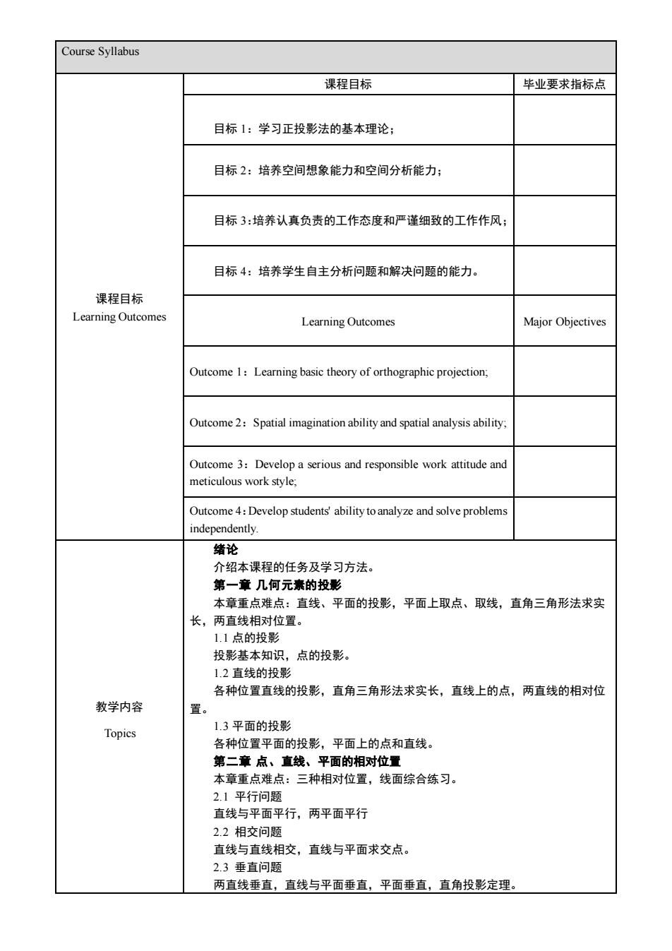
Course Syllabus 课程目标 Learning Outcomes 课程目标 毕业要求指标点 目标 1:学习正投影法的基本理论; 目标 2:培养空间想象能力和空间分析能力; 目标 3:培养认真负责的工作态度和严谨细致的工作作风; 目标 4:培养学生自主分析问题和解决问题的能力。 Learning Outcomes Major Objectives Outcome 1:Learning basic theory of orthographic projection; Outcome 2:Spatial imagination ability and spatial analysis ability; Outcome 3:Develop a serious and responsible work attitude and meticulous work style; Outcome 4:Develop students' ability to analyze and solve problems independently. 教学内容 Topics 绪论 介绍本课程的任务及学习方法。 第一章 几何元素的投影 本章重点难点:直线、平面的投影,平面上取点、取线,直角三角形法求实 长,两直线相对位置。 1.1 点的投影 投影基本知识,点的投影。 1.2 直线的投影 各种位置直线的投影,直角三角形法求实长,直线上的点,两直线的相对位 置。 1.3 平面的投影 各种位置平面的投影,平面上的点和直线。 第二章 点、直线、平面的相对位置 本章重点难点:三种相对位置,线面综合练习。 2.1 平行问题 直线与平面平行,两平面平行 2.2 相交问题 直线与直线相交,直线与平面求交点。 2.3 垂直问题 两直线垂直,直线与平面垂直,平面垂直,直角投影定理
2.4综合问题分析 第三章投影变换 本章重点难点:直线与平面投影变换及其应用 3.1投影变换概过 3.2变换投影面法 直线的三种变换,平面的三种变换,用换面法求直线实长、倾角,平面实 长、倾角,线面夹角等。 第四章曲线与曲面 本章重点难点:螺旋线的画法,螺旋面的画法 4.1曲线的形成与投影 讲解圆柱螺旋线的形成与作图方法。 4.2曲面的形成与表达方法 进解正螺旅面的形成和投影画法 第五章立体及其表面交线的投影 本章重点难点:立体的投影,立体截切及相贯线求做, 5.1平面立体及其截切 平面立体的投影,平面与立体相交,平面体与平面体相交。 5.2曲面立体及其截切 曲面立体的投影, 曲面立体截交线的求法,平面体与曲面体相交 5.3曲面体与曲面体相交 曲面立体相贯线的做法。 第六章轴测投影 本章重点难点:正等轴测图求做 6.1轴测投影基本知识 62正等测 第七章绘图基本知识 本章重点难点:绘图基本规定 7.1绘图基本规定 7.2平面图形分析及绘图步骤 第八章组合体的视图 本章重点难点:三视图的画法,组合体读图:尺寸标注。 8.1三视图的形成及其特性 8.2组合体的组合方式 83二视图的画法 8.4读组合体的视图 读图基本方法,不同类型组合体读图方法以及例题讲解 8.5组合体的尺寸标注 尺寸标注规范、注意问题,基本体、组合体尺寸标注方法。 第九章机件的表达方法 太音质占谁占, 各种表达方法的介绍及综合运用 91视图 六个基本视图,局部视图,斜视图,第三角画法简介。 9.2剖视图 剖视图的概念,全剖、半剖、局部剖。 93新面图 9.4简化画法及其他规定画法 9.5综合表达举例 第十章零件图 本章重点难点:零件图的尺寸标注与视图表达,零件的技术要求
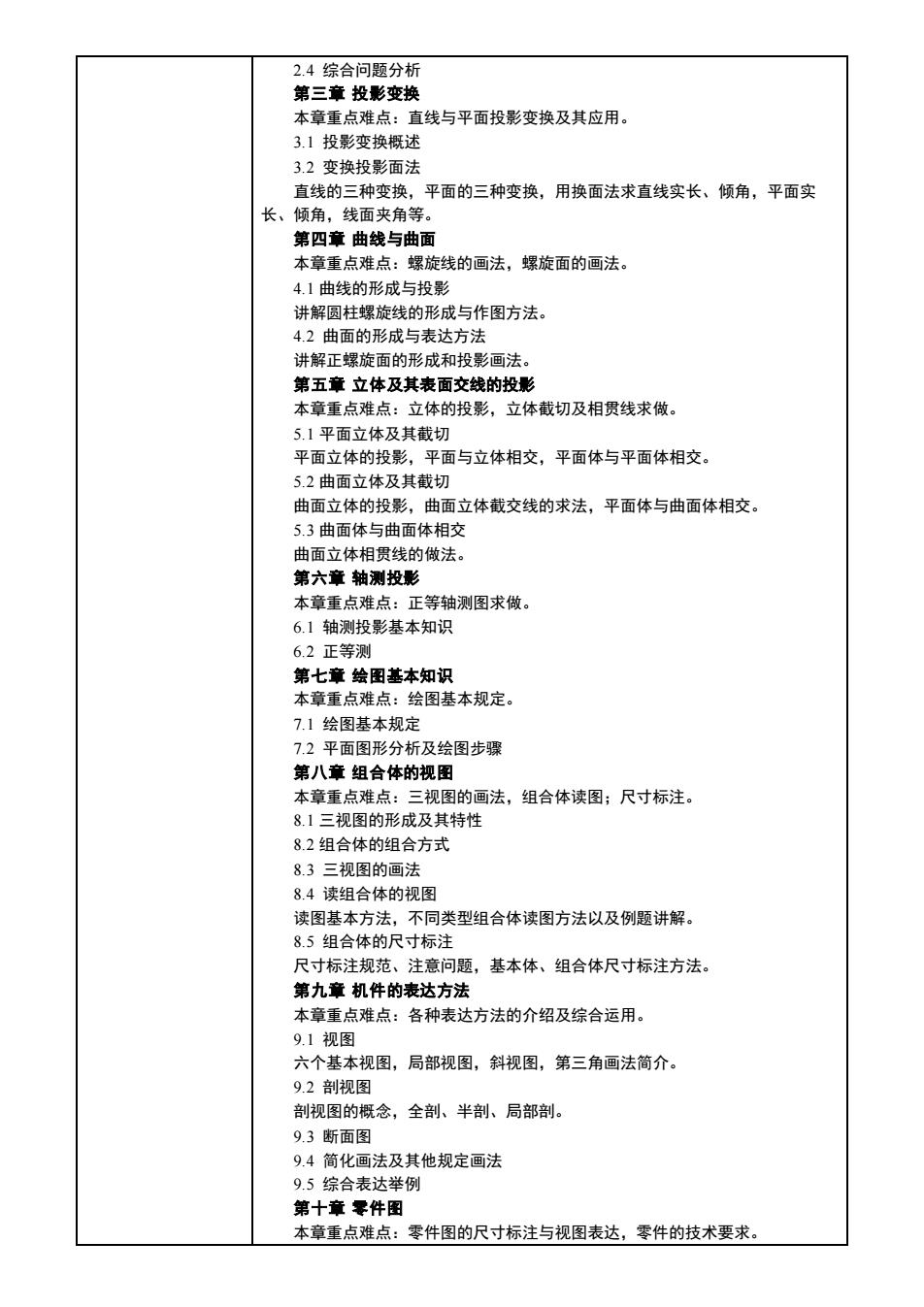
2.4 综合问题分析 第三章 投影变换 本章重点难点:直线与平面投影变换及其应用。 3.1 投影变换概述 3.2 变换投影面法 直线的三种变换,平面的三种变换,用换面法求直线实长、倾角,平面实 长、倾角,线面夹角等。 第四章 曲线与曲面 本章重点难点:螺旋线的画法,螺旋面的画法。 4.1 曲线的形成与投影 讲解圆柱螺旋线的形成与作图方法。 4.2 曲面的形成与表达方法 讲解正螺旋面的形成和投影画法。 第五章 立体及其表面交线的投影 本章重点难点:立体的投影,立体截切及相贯线求做。 5.1 平面立体及其截切 平面立体的投影,平面与立体相交,平面体与平面体相交。 5.2 曲面立体及其截切 曲面立体的投影,曲面立体截交线的求法,平面体与曲面体相交。 5.3 曲面体与曲面体相交 曲面立体相贯线的做法。 第六章 轴测投影 本章重点难点:正等轴测图求做。 6.1 轴测投影基本知识 6.2 正等测 第七章 绘图基本知识 本章重点难点:绘图基本规定。 7.1 绘图基本规定 7.2 平面图形分析及绘图步骤 第八章 组合体的视图 本章重点难点:三视图的画法,组合体读图;尺寸标注。 8.1 三视图的形成及其特性 8.2 组合体的组合方式 8.3 三视图的画法 8.4 读组合体的视图 读图基本方法,不同类型组合体读图方法以及例题讲解。 8.5 组合体的尺寸标注 尺寸标注规范、注意问题,基本体、组合体尺寸标注方法。 第九章 机件的表达方法 本章重点难点:各种表达方法的介绍及综合运用。 9.1 视图 六个基本视图,局部视图,斜视图,第三角画法简介。 9.2 剖视图 剖视图的概念,全剖、半剖、局部剖。 9.3 断面图 9.4 简化画法及其他规定画法 9.5 综合表达举例 第十章 零件图 本章重点难点:零件图的尺寸标注与视图表达,零件的技术要求
101零件的分举。零件图的内容 10.2零件构形设计与表达方案的选择 分四类零件介绍其视图表达的特点,主视图的选择原则 10.3零件图的尺寸标注 零件图尺寸基准的选择,零件图尺寸标注应注意的问题。 10.4零件图上的技术要求 表而结物。公美与配合。形位公美 10.5零件测绘方法 10.6看零件图的方法 第十一章标准件与常用件 本章重点难点:螺纹的标记与画法,直齿圆柱齿轮的参数计算与画法 11.1螺纹及其规定画法和标注 螺栓连接、双头螺柱连接、螺钉连接的画法。 11.3键、销及其连接画法 11.4齿轮、蜗杆、蜗轮 直货圆柱齿轮的画法 1.5滚动轴承 弹簧 第十二章装配图 本章重点难点:装配图的表达,拆画零件图。 12.1装配图的内容 122装配图的表达方法 12.3装配图上的尺寸标注和技术要求 12.4装配图中零件的序号 12.5装配工艺结构 12.6部件测绘和装配图画法 127读装配图与拆画零件图 The task and learning methods of the course are introduced. Chapter 1 projection of geometric elements Key points in this chapter:taking points on the straight line,taking points on the lane,taking the line. 1.1 projection of point Basic knowledge of projection,projection of a point. 1.2 projection of lines Projection of several kinds of lines,the right triangle method,the point on line,the elative position of two lines. 1.3projection of planes A projection of various position planes,points and linesona plane Chapter 2:the relative position of points,lines and planes Key points in this chapter:rectangular projection theorem,and the comprehensive 2.1 parallel problem Intersection of two lines,intersecting point between a line and a plane 2.3 vertical problem Vertical relationship between two lines,a line and a plane,two planes,rectangular iection theorem
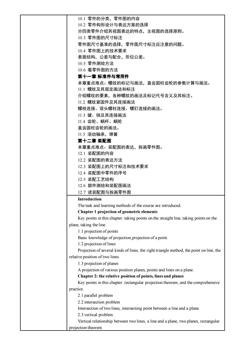
10.1 零件的分类,零件图的内容 10.2 零件构形设计与表达方案的选择 分四类零件介绍其视图表达的特点,主视图的选择原则。 10.3 零件图的尺寸标注 零件图尺寸基准的选择,零件图尺寸标注应注意的问题。 10.4 零件图上的技术要求 表面结构,公差与配合,形位公差。 10.5 零件测绘方法 10.6 看零件图的方法 第十一章 标准件与常用件 本章重点难点:螺纹的标记与画法,直齿圆柱齿轮的参数计算与画法。 11.1 螺纹及其规定画法和标注 介绍螺纹的要素,各种螺纹的画法及标记代号含义及其标注。 11.2 螺纹紧固件及其连接画法 螺栓连接、双头螺柱连接、螺钉连接的画法。 11.3 键、销及其连接画法 11.4 齿轮、蜗杆、蜗轮 直齿圆柱齿轮的画法。 11.5 滚动轴承,弹簧 第十二章 装配图 本章重点难点:装配图的表达,拆画零件图。 12.1 装配图的内容 12.2 装配图的表达方法 12.3 装配图上的尺寸标注和技术要求 12.4 装配图中零件的序号 12.5 装配工艺结构 12.6 部件测绘和装配图画法 12.7 读装配图与拆画零件图 Introduction The task and learning methods of the course are introduced. Chapter 1 projection of geometric elements Key points in this chapter: taking points on the straight line, taking points on the plane, taking the line. 1.1 projection of points Basic knowledge of projection,projection of a point. 1.2 projection of lines Projection of several kinds of lines, the right triangle method, the point on line, the relative position of two lines. 1.3 projection of planes A projection of various position planes, points and lines on a plane. Chapter 2: the relative position of points, lines and planes Key points in this chapter: rectangular projection theorem, and the comprehensive practice. 2.1 parallel problem 2.2 intersection problem Intersection of two lines, intersecting point between a line and a plane. 2.3 vertical problem Vertical relationship between two lines, a line and a plane, two planes, rectangular projection theorem
2.4 comprehensive problem analysis Chapter 3:proiection transformation Key points in projection ransformations of planes,application of projection transformation. 3.1 projection transformation overview 3.2 proiection transform method Three kinds of transformation of a line three kinds of transformation of a plane alculating the real size(aplane)by method Chapter 4:curve and surface The key points in this chapter:drawing of spiral surface. 4.I formation and proiection of curve The drawing method of 4 2 forma method Explain the formation and projection of equilateral spiral surface Chapter 5:the projection of the surface and itsintersection Key points in this chapter:cutting and intersection line 5 I planar solid and its cutting two planar solids. 5.2 curved surface and its cutting The projection of the curved surface and the intersection of the curved surface and the intersection of the planar solid and the curved surface 5.3the intersection of curved surface and curved surface The drawing method of curved surface intersecting line Chapter 6:axonometric projection Key points in this chapter:isometric axonometric projection 6.I basic knowledge of axonometric projection 6 2 isometric axo Chapter7:basic knowledge of drafting standards Key points in this chapter:basic drawing rules. 7.I basic drafting standards 7.2 plane graphics analysis and its drawing steps Chapter:view of the composite solids 8.I the formation and characteristics of three views 8.2 combination mode of composite solid 8.3 drawing steps of three views 8.4 read drav gsof composite oli s of reading drawings,different types of reading methods on different composite solid,examples. 8.5 dimensioning of composite solid Standards of composite solid dimensioning.attention problems.dimensioning ethod of basic solid and composite solid. Chapter 9 expres n metho ne parts Key points in this chapter:introduction and comprehensive application of various methods of expression. 9.1 views
2.4 comprehensive problem analysis Chapter 3: projection transformation Key points in this chapter: projection transformations of lines, projection transformations of planes, application of projection transformation. 3.1 projection transformation overview 3.2 projection transform method Three kinds of transformation of a line, three kinds of transformation of a plane, calculating the real size of line or angle of a line (or a plane or a line and a plane) by projection transform method. Chapter 4: curve and surface The key points in this chapter: drawing of spiral surface. 4.1 formation and projection of curve The formation and drawing method of cylindrical helix. 4.2 formation and expression method of surface Explain the formation and projection of equilateral spiral surface. Chapter 5: the projection of the surface and its intersection Key points in this chapter: cutting and intersection line. 5.1 planar solid and its cutting The projection of a planar solid, a planar solid cut by a plane, intersecting between two planar solids. 5.2 curved surface and its cutting The projection of the curved surface and the intersection of the curved surface and the intersection of the planar solid and the curved surface. 5.3 the intersection of curved surface and curved surface The drawing method of curved surface intersecting line. Chapter 6: axonometric projection Key points in this chapter: isometric axonometric projection. 6.1 basic knowledge of axonometric projection 6.2 isometric axonometric projection Chapter 7: basic knowledge of drafting standards Key points in this chapter: basic drawing rules. 7.1 basic drafting standards 7.2 plane graphics analysis and its drawing steps Chapter 8: view of the composite solids Key points in this chapter: reading drawings of composite solid; dimensioning of composite solid. 8.1 the formation and characteristics of three views 8.2 combination mode of composite solid 8.3 drawing steps of three views 8.4 read drawings of composite solid The basic methods of reading drawings, different types of reading methods on different composite solid, examples. 8.5 dimensioning of composite solid Standards of composite solid dimensioning, attention problems, dimensioning method of basic solid and composite solid. Chapter 9: expression method of machine parts Key points in this chapter: introduction and comprehensive application of various methods of expression. 9.1 views