Measurement of Forced Vibration with Boer Resonance Spectrometer In manufacturing and construction industries,the resonance phenomenon caused by forced vibration has attracted a lot of interest.It has both adverse and beneficial effects.Many electro-acoustic devices are based on the resonance effect.In addition 'resonance'is also an important concept in microscopic phenomena.For instance,nuclear magnetic resonance and paramagnetic resonance techniques are very useful in the study the microscopic structure of matter. Forced vibration is fully characterized by its amplitude-frequency and phase-frequency characteristics. In the current experiment,we use Boer resonance spectrometer to measure the amplitude-frequency and phase-frequency characteristics of forced vibration,and measure dynamic quantities like phase difference by stroboscopic method.The experiment also requires considerable data processing and error analysis. Experimental Objectives 1.Study the amplitude-frequency and phase-frequency characteristics of the wheel pendulum under forced vibration in the Boer resonance spectrometer 2.Study the effects of damping torque on forced vibration and resonance. 3.Learn to measure dynamic quantities using the stroboscopic method Experimental Principle The vibration of an object under continuous periodic external driving is known as forced vibration,and the periodic external driving is known as the external driving force.If the external driving force is harmonic,the forced vibration is also harmonic at steady state,whose amplitude is a constant which is determined by the driving frequency,the natural vibration frequency without damping,and the damping coefficient.Under the forced vibration conditions,the system is also subjected to the restoring force and the damping force in addition to driving force.Therefore,there exists certain phase difference among the displacement,speed,and driving force at the steady state. Resonance happens when the driving frequency equals the system's natural vibration frequency. At resonance,the vibration amplitude reaches the maximum and has a phase difference with the driving force of 90. The current experiment studies the forced vibration characteristics of the wheel pendulum under the elastic restoring torque and the electromagnetic damping torque,which can demonstrate many vibration phenomena directly.When the wheel pendulum is subjected to periodic driving torqueM=Mocosin addition to air and electromagnetic damping (damping torque is) the equation of motion is: id di=-ko-b do Mo cos @t (1) dt J is the moment inertia of the wheel pendulum,-ke is the elastic restoring torque,Mo is the
Measurement of Forced Vibration with Boer Resonance Spectrometer In manufacturing and construction industries, the resonance phenomenon caused by forced vibration has attracted a lot of interest. It has both adverse and beneficial effects. Many electro-acoustic devices are based on the resonance effect. In addition, ‘resonance’ is also an important concept in microscopic phenomena. For instance, nuclear magnetic resonance and paramagnetic resonance techniques are very useful in the study the microscopic structure of matter. Forced vibration is fully characterized by its amplitude-frequency and phase-frequency characteristics. In the current experiment, we use Boer resonance spectrometer to measure the amplitude-frequency and phase-frequency characteristics of forced vibration, and measure dynamic quantities like phase difference by stroboscopic method. The experiment also requires considerable data processing and error analysis. Experimental Objectives 1. Study the amplitude-frequency and phase-frequency characteristics of the wheel pendulum under forced vibration in the Boer resonance spectrometer 2. Study the effects of damping torque on forced vibration and resonance. 3. Learn to measure dynamic quantities using the stroboscopic method Experimental Principle The vibration of an object under continuous periodic external driving is known as forced vibration, and the periodic external driving is known as the external driving force. If the external driving force is harmonic, the forced vibration is also harmonic at steady state, whose amplitude is a constant which is determined by the driving frequency, the natural vibration frequency without damping, and the damping coefficient. Under the forced vibration conditions, the system is also subjected to the restoring force and the damping force in addition to driving force. Therefore, there exists certain phase difference among the displacement, speed, and driving force at the steady state. Resonance happens when the driving frequency equals the system’s natural vibration frequency. At resonance, the vibration amplitude reaches the maximum and has a phase difference with the driving force of 90 °. The current experiment studies the forced vibration characteristics of the wheel pendulum under the elastic restoring torque and the electromagnetic damping torque, which can demonstrate many vibration phenomena directly. When the wheel pendulum is subjected to periodic driving torque in addition to air and electromagnetic damping (damping torque is ), the equation of motion is: M t dt d k b dt d J cos 2 0 2 = − − + (1) is the moment inertia of the wheel pendulum, is the elastic restoring torque, is the d b dt M M t = 0 cos − J −k M0
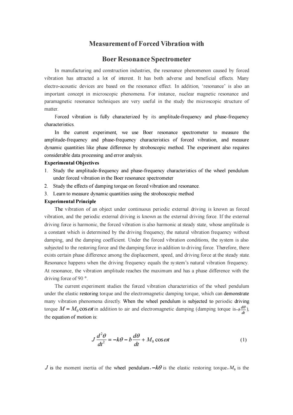
amplitude of the driving torque,o is the angular frequency of the driving force.Assuming m=M 2二万2B、6 J Then Eq.(1)can be written as: a2+2B9® d20 -+oθ=m cos ot (2) dt If mcosoot=0,Eq.(2)is damped vibration equation. If Balso equal to 0,Eq.(2)is a harmonic vibration equation,the intrinsic vibration frequency of the system is The general solution of Eq.(2)is 0=0,ecos(o,t+a)+日,cos(ot+) (3) From Eq.(3),we know that the solution of forced vibration can be separated into two parts: First transient part,ecos()is related to initial conditions and will decay to zero after a certain period of time. Second steady-state part indicates that energy is fed to the system continuously by the driving torque acting on the wheel pendulum,and finally the system reaches a steady state. m 82= (4) Vo2-o2)2+4B2o2 The phase difference between the vibrating body and the driving torque is 2Bo φ=arctg 0,2-0 (5) From Eqs.(4)and (5),it is obvious that the amplitude and phase differenced are both dependent on the driving torque M,angular frequency,system natural frequency and damping coefficient B,and are irrelevant with the initial conditions. Under the extreme condition ofresonance will happens and the driving angular frequency=-22,at resonance,0 reaches maximum. and are the resonance angular frequency and amplitude respectively: 0,=√02-2B (6) m 8= (7) 2B10o2-B2 It is clear from Eqs.(6)and(7),the smaller the damping coefficient B,the closer the resonance frequency is to the natural frequency and larger the amplitude , Figures 1-2 show the amplitude-frequency and phase-frequency characteristics of forced vibration at different B
amplitude of the driving torque, is the angular frequency of the driving force . Assuming J M m J b J k 2 0 0 = ,2 = , = Then Eq.(1)can be written as: m t dt d dt d 2 cos 2 2 0 2 + + = (2) If m t cos 0 = ,Eq.(2)is damped vibration equation. If also equal to 0,Eq.(2)is a harmonic vibration equation,the intrinsic vibration frequency of the system is The general solution of Eq.(2)is 1 2 cos( ) cos( ) t f e t t − = + + + (3) From Eq.(3),we know that the solution of forced vibration can be separated into two parts: First transient part, is related to initial conditions and will decay to zero after a certain period of time. Second steady-state part indicates that energy is fed to the system continuously by the driving torque acting on the wheel pendulum, and finally the system reaches a steady state. 2 2 2 2 2 0 2 ( ) 4 − + = m (4) The phase difference between the vibrating body and the driving torque is 2 2 0 2 − = arctg (5) From Eqs. (4) and (5) , it is obvious that the amplitude and phase difference are both dependent on the driving torque , angular frequency , system natural frequency and damping coefficient , and are irrelevant with the initial conditions. Under the extreme condition of , resonance will happens and the driving angular frequency , at resonance, θ reaches maximum. and are the resonance angular frequency and amplitude respectively: 2 2 r = 0 − 2 (6) 2 2 2 0 − = m r (7) It is clear from Eqs. (6) and (7), the smaller the damping coefficient , the closer the resonance frequency is to the natural frequency and larger the amplitude . Figures 1-2 show the amplitude-frequency and phase-frequency characteristics of forced vibration at different . 0 1 cos( ) t f e t − + 2 2 2 2 2 0 [( ) 4 ] 0 − + = 2 2 = − 0 2 2 M 0 r r r
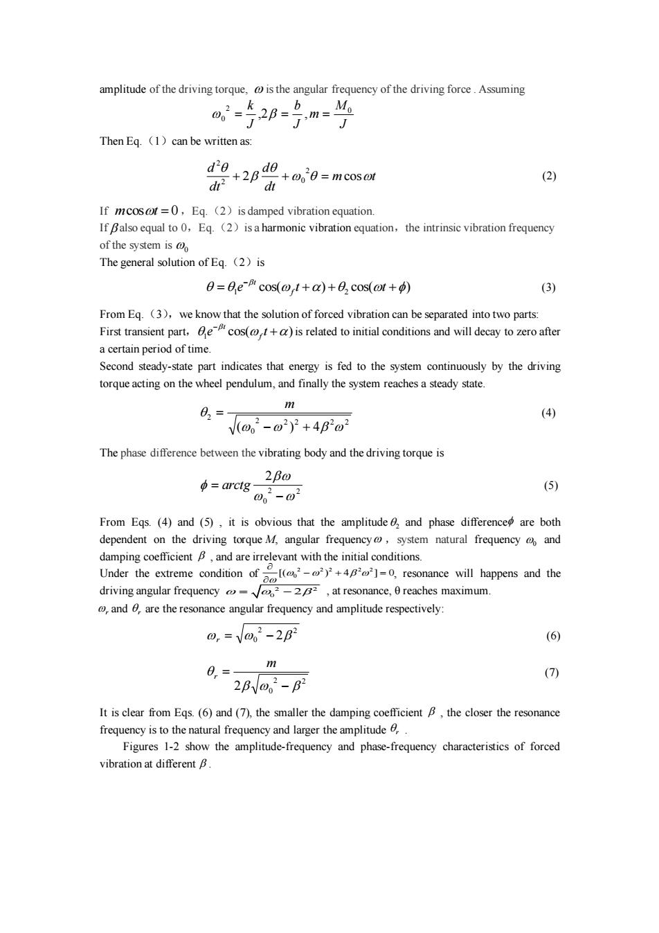
B1<B2<B3 1.0 图-1 图-2 Experimental apparatus BG-2 type Born resonance spectrometer is composed of a vibration stage and an electrical control box.The vibration stage is shown in Fig.3,where a copper wheel pendulum is mounted on a rack.One end of the scroll spring is connected to the shaft of the wheel pendulum,and the other end is fixed on a post on the rack.The wheel pendulum can rotate freely around the shaft under the elastic restoring force of the spring.There are grooves at the perimeter of the wheel, with one of them much longer than the other.A photoelectric sensor connected to the electrical box is aligned with the long groove which is used to measure the vibration amplitude of the wheel pendulum (angular amplitude)and its frequency.There is a pair of coils with ion cores at the bottom of the rack.The wheel pendulum is positioned between the coils.The wheel pendulum is subjected to a damping force when there is current in the coils according to the law of electromagnetic induction.The damping force can be changed by changing the current.In order to make the wheel pendulum undergo forced vibration,an eccentric wheel is connected to the motor shaft which drives the pendulum through a link mechanism.Plexiglass disk with mark lines is attached to the motor shaft,it can be used to read the phase difference as it rotates with the motor. Voltage applied to the motor can be accurately changed by the ten-lap regulating knob so that the rotational speed of the motor is adjustable within the experimental range(30 to 45 rev/min).The rotation speed is extremely stable owing to special speed maintenance device in the circuit and the motor is a special motor with speedometer and the inertia is small.Plexiglass disk on the motor is equipped with two light blockers.A photoelectric sensor(driving torque signal)is mounted on the angular position dial disk(at 90)which is also connected to the control box in order to measure the cycle of the driving torque. ( Figure 3
图-1 图-2 0 1.0 ω/ω0 1.0 ω/ω0 θ 0 -π/2 -π β1 β2 β3 β1<β2<β3 β1<β2 β2 β1 φ Experimental apparatus BG-2 type Born resonance spectrometer is composed of a vibration stage and an electrical control box. The vibration stage is shown in Fig. 3, where a copper wheel pendulum is mounted on a rack. One end of the scroll spring is connected to the shaft of the wheel pendulum, and the other end is fixed on a post on the rack. The wheel pendulum can rotate freely around the shaft under the elastic restoring force of the spring. There are grooves at the perimeter of the wheel, with one of them much longer than the other. A photoelectric sensor connected to the electrical box is aligned with the long groove which is used to measure the vibration amplitude of the wheel pendulum (angular amplitude) and its frequency. There is a pair of coils with ion cores at the bottom of the rack. The wheel pendulum is positioned between the coils. The wheel pendulum is subjected to a damping force when there is current in the coils according to the law of electromagnetic induction. The damping force can be changed by changing the current. In order to make the wheel pendulum undergo forced vibration, an eccentric wheel is connected to the motor shaft which drives the pendulum through a link mechanism. Plexiglass disk with mark lines is attached to the motor shaft, it can be used to read the phase difference as it rotates with the motor. Voltage applied to the motor can be accurately changed by the ten-lap regulating knob so that the rotational speed of the motor is adjustable within the experimental range (30 to 45 rev / min). The rotation speed is extremely stable owing to special speed maintenance device in the circuit and the motor is a special motor with speedometer and the inertia is small. Plexiglass disk on the motor is equipped with two light blockers. A photoelectric sensor (driving torque signal) is mounted on the angular position dial disk (at 90 °) which is also connected to the control box in order to measure the cycle of the driving torque. Figure 3
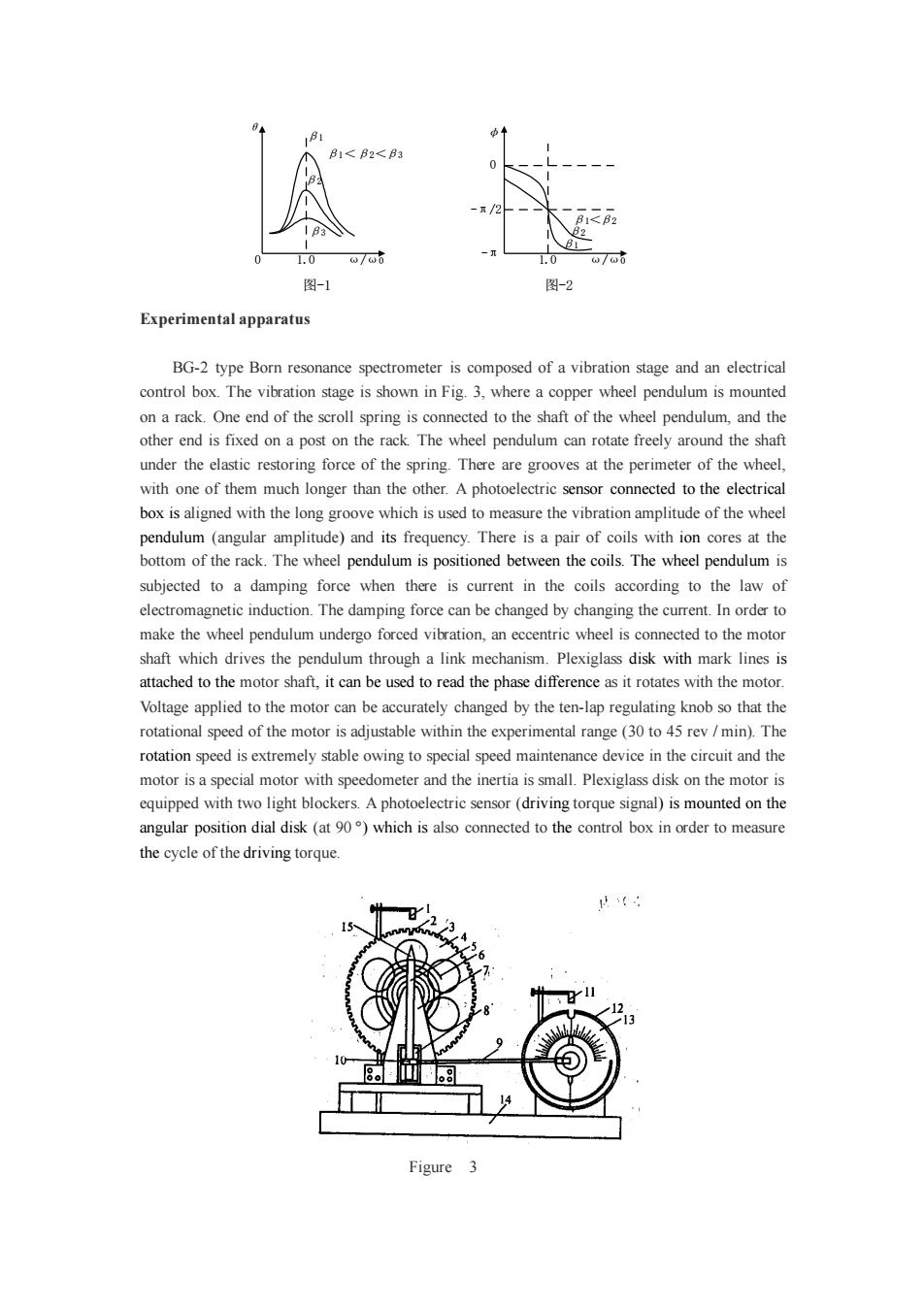
1.Photoelectric sensor;2.Long groove;3.Short groove;4.Copper wheel pendulum;5. joystick;6.Scroll spring;7.Supporting rack;8.Damping wire;9.Link rod;10.Adjustment screw of the joystick;11.Photoelectric sensor;12.Angular position dial disk;13.Plexiglass disk;14. Base;15.Clamping screw The phase difference between the wheel pendulum and the external torque is measured by a small flashlight.The flashlight is controlled by the photoelectric sensor.Whenever the long groove on the wheel pendulum pass through the balance position,the photoelectric sensor is blocked, which triggers the flashlight to flash.Under steady state conditions,the marker line on the plexiglass seems to be"frozen"at certain dial position under the flashlight illumination,which is known as the stroboscopic phenomenon.The dial number can be easily read out with an error less than 2 Amplitude of the vibration is measured by the number of grooves passed by the photoelectric sensor,which can be read out from a digital display with an error less 2. The front and back panels of the electric control box are shown in Figs 4-5. The three-digit number on the left shows the vibration amplitude of the wheel pendulum.The five-digit number on the right displays the cycle period of the vibration with an accuracy of 103s. When the“cycle'”switch is set to“I”,it displays the time period of one cycle,.and when the switch is set to "10",it displays the time period of 10 cycles.The reset button works only when the switch is set to“10”. The speed adjustment button,which is a ten-lap potentiometer,can be used to precisely adjust the speed of the motor,i.e,the cycle of the driving torque.The dial is used for rough estimate of the driving period when setting the potentiometer. The damping current switch can be used to change the DC current through the damping coil in order to change the damping coefficient of the wheel pendulum system.The switch can have six positions,the damping current at 0'is zero,at '1'is approximately 0.2A,at'5'reaches the maximum about 0.6A.The damping current is fed by a 15V power supply.The selection is based on experimental requirements(typically '3'or'4'). 振幅显示 周期显示(秒) 强追力周期 BG-2型波耳共摄仪 10▣10 00 O 同济大学学中电同期选择复位电帆开关闪光打电 物理实验室监制 图-4前面板
1. Photoelectric sensor; 2. Long groove; 3. Short groove; 4. Copper wheel pendulum; 5. joystick; 6. Scroll spring; 7. Supporting rack; 8. Damping wire; 9.Link rod;10. Adjustment screw of the joystick; 11. Photoelectric sensor; 12. Angular position dial disk; 13. Plexiglass disk; 14. Base; 15. Clamping screw The phase difference between the wheel pendulum and the external torque is measured by a small flashlight. The flashlight is controlled by the photoelectric sensor. Whenever the long groove on the wheel pendulum pass through the balance position, the photoelectric sensor is blocked, which triggers the flashlight to flash. Under steady state conditions, the marker line on the plexiglass seems to be “frozen” at certain dial position under the flashlight illumination, which is known as the stroboscopic phenomenon. The dial number can be easily read out with an error less than 2 °. Amplitude of the vibration is measured by the number of grooves passed by the photoelectric sensor, which can be read out from a digital display with an error less 2 °. The front and back panels of the electric control box are shown in Figs 4-5. The three-digit number on the left shows the vibration amplitude of the wheel pendulum. The five-digit number on the right displays the cycle period of the vibration with an accuracy of 10-3 s. When the “cycle” switch is set to “1”, it displays the time period of one cycle, and when the switch is set to “10”, it displays the time period of 10 cycles. The reset button works only when the switch is set to “10”. The speed adjustment button, which is a ten-lap potentiometer, can be used to precisely adjust the speed of the motor, i.e., the cycle of the driving torque. The dial is used for rough estimate of the driving period when setting the potentiometer. The damping current switch can be used to change the DC current through the damping coil in order to change the damping coefficient of the wheel pendulum system. The switch can have six positions, the damping current at ‘0’ is zero, at ‘1’ is approximately 0.2A, at ‘5’ reaches the maximum about 0.6A. The damping current is fed by a 15V power supply. The selection is based on experimental requirements (typically ‘3’ or ‘4’). 强迫力周期 B G - 2型波耳共振仪 周期显示(秒) 0 周期选择 复位 电机开关 闪光灯 电源 10 1 振幅显示 同济大学教学科研加工中心制造 物理实验室监制 1 2 3 4 5 图-4 前面板
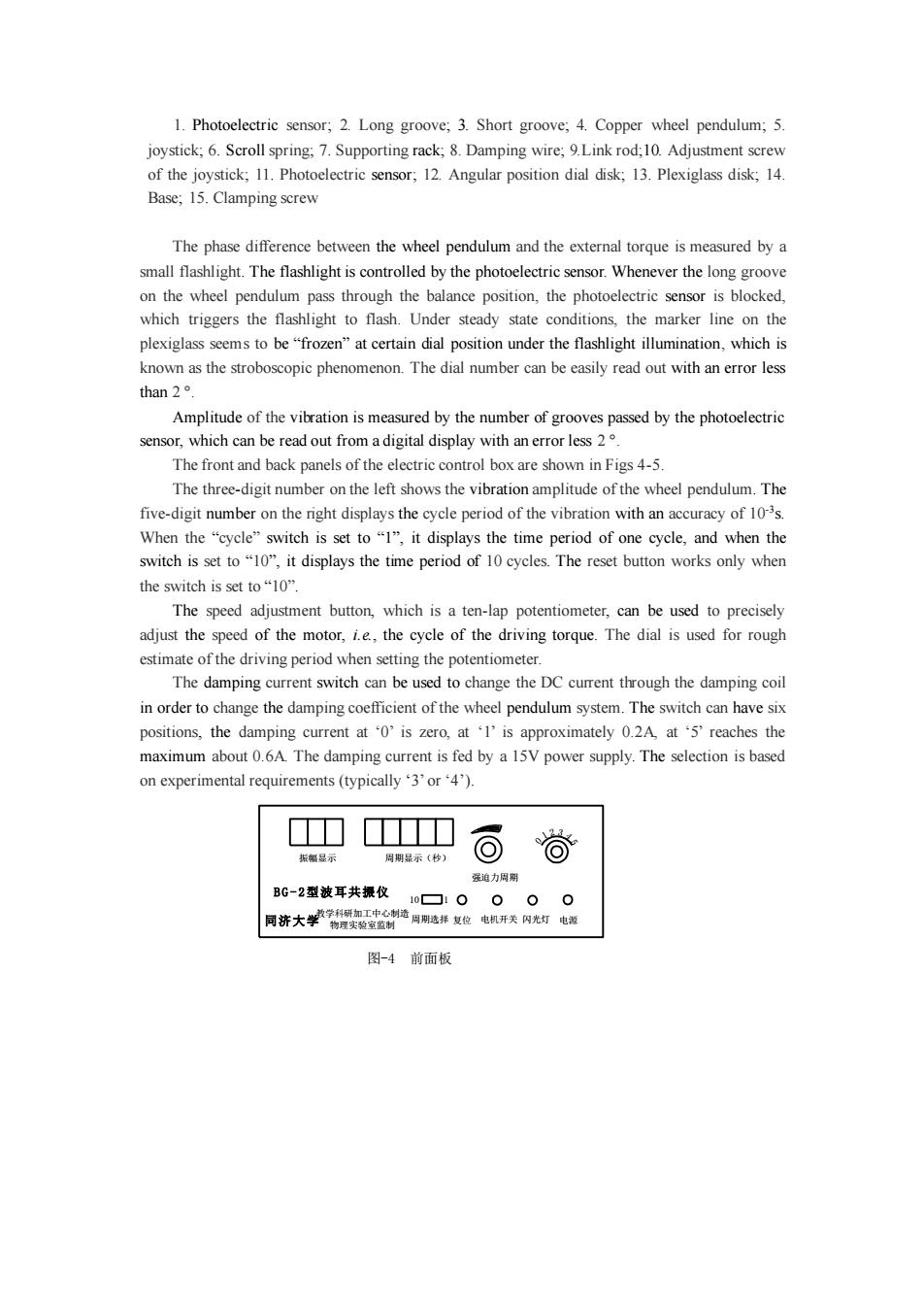
闪光灯 阻尼线圈电机 振输入用明入 图-5后面板 Flashlight switch is used to control whether to flash or not.When the switch is set to ON position,it will generate flash as long as the long groove pass through the balance position,the marker line on the plexiglass disk seems to point to constant reading on the angular dial disk (actually the pointer on the plexiglass disk is rotating continuously with constant speed).From which the phase difference value can be measured.Normally the switch is set to OFF position to save the lifetime of the flash tube,and to ON position only when measuring the phase difference. Motor switch is used to control the motor's rotation,and the motor must be off when measuring the damping coefficient and the amplitude and the natural vibration frequency curve. Electrical control box are connected with the flashlight and the Boer resonance spectrometer by special cables and are free of wiring errors. Experimental Contents 1.Measure the damping coefficient B As mentioned above,damping vibration is measured without driving force.Motor power must be turned off and the plexiglass marker line should be set at the 0 position. Damping switch is set to 2',once selected,it can not be changed during the experiment.Turn the wheel pendulum between 130-150 by hand,and read out the amplitude from period to period from the display window . Since there is no driving force,the solution of eq.(1)is 0=0e-cos(ot+a) (8) so that 0=be-,=de-0=de-aT) Also using InIn e 日8,em=i-)Br (9) B can be calculated,where 6,are the amplitude during the ith and jth cycle.T is the mean cycle value of the damping vibration.It can be calculated by averaging several corresponding cycles with different amplitudes.The B value can be calculated using the step-difference method. Appendix:data tables Table 1 B value calculation log sheet damping switch position at Amplitude Amplitude 046
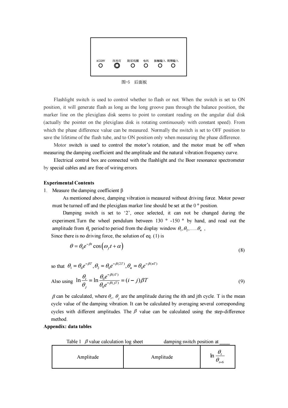
AC220V 闪光灯 阻尼线圈 电机 振幅输入 周期输入 图-5 后面板 Flashlight switch is used to control whether to flash or not. When the switch is set to ON position, it will generate flash as long as the long groove pass through the balance position, the marker line on the plexiglass disk seems to point to constant reading on the angular dial disk (actually the pointer on the plexiglass disk is rotating continuously with constant speed). From which the phase difference value can be measured. Normally the switch is set to OFF position to save the lifetime of the flash tube, and to ON position only when measuring the phase difference. Motor switch is used to control the motor’s rotation, and the motor must be off when measuring the damping coefficient and the amplitude and the natural vibration frequency curve. Electrical control box are connected with the flashlight and the Boer resonance spectrometer by special cables and are free of wiring errors. Experimental Contents 1. Measure the damping coefficient β As mentioned above, damping vibration is measured without driving force. Motor power must be turned off and the plexiglass marker line should be set at the 0 ° position. Damping switch is set to ‘2’, once selected, it can not be changed during the experiment.Turn the wheel pendulum between 130 ° -150 ° by hand, and read out the amplitude from period to period from the display window , Since there is no driving force, the solution of eq. (1) is 0 cos( ) t f e t − = + (8) so that Also using (9) can be calculated, where , are the amplitude during the ith and jth cycle. T is the mean cycle value of the damping vibration. It can be calculated by averaging several corresponding cycles with different amplitudes. The value can be calculated using the step-difference method. Appendix: data tables Table 1 value calculation log sheet damping switch position at ____ Amplitude Amplitude 6 ln i+ i i j 0 1 2 , ,...... n ( ) 0 ( ) 0 ln ln ( ) iT i jT j e i j T e − − = = − (2 ) ( ) 1 0 2 0 0 , , T T nT n e e e − − − = = =