20 Introduction Chap.1 to Section 1.3.1.Fo is allowed to take any value and all members of the set are distinct.in the sense that if k2.then ser(t)s2(). From the basic signals in (1.3.16)we can construct a linear combination of harmonically related complex exponentials of the form xa(1)= (1.3.17) where c.=0.1.+2....are arbitrary complex constants.The signal x(t) is periodic with fundamental period T=1/Fo.and its representation in terms of (1.3.17)is called the Fourier series expansion for xe(r).The complex-valued constants are the Fourier series coefficients and the signal se()is called the kth harmonic ofx(). Discrete-time exponentials.Since a discrete-time complex exponential is periodic if its relative frequency is a rational number,we choosefo=1/N and we define the sets of harmonically related complex exponentials by 5联(》=e2mkf,k=0,±1.±2., 1.3.18) In contrast to the continuous-time case.we note that Skiw(n)=ejzxmNiIN =e2ns(n)=se(n) This means that.consistent with(1.3.10).there are only N distinct periodic complex exponentials in the set described by (1.3.18).Furthermore.all members of the set have a common period of N samples.Clearly.we can choose any consecutive N complex exponentials.say from k =no to k=nn+N-I to form a harmonically related set with fundamental frequency fo 1/N.Most often.for convenience. we choose the set that corresponds to no =0.that is.the set 5m)=e2mkn.k=0.1.2..N-1 (1.3.19) As in the case of continuous-time signals.it is obvious that the linear com- bination x(n)= (1.3.20) ★0 t=0 results in a periodic signal with fundamental period N.As we shall see later. this is the Fourier series representation for a periodic discrete-time sequence with Fourier coefficients c.The sequence se(n)is called the kth harmonic of x(n). Example 1.3.1 Stored in the memory of a digital signal processor is one cycle of the sinusoidal signal x(n)=sin where 6=2xg/N.where g and N are integers
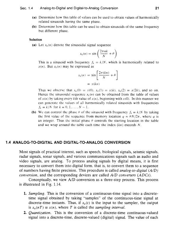
Sec.1.4 Analog-to-Digital and Digital-to-Analog Conversion 21 (a)Determine how this table of values can be used to obtain values of harmonically related sinusoids having the same phase. (b)Determine how this table can be used to obtain sinusoids of the same frequency but different phase. Solution (a)Let x(n)denote the sinusoidal signal sequence 2xnk x(n)=sin This is a sinusoid with frequencyf=k/N.which is harmonically related to x(n).Butx:(n)may be expressed as 2m(kn) (n)=sin =x(依n) Thus we observe that (0=r().(1)=x().x:(2)=x(2k).and so on. Hence the sinusoidal sequence x(n)can be obtained from the table of values of x(n)by taking every kth value of x(n).beginning with x(0).In this manner we can gencrate the vatues of all harmonically related sinusoids with frequencies i=k/八fark=0.I.,N-【. (b)We can control the phase 6 of the sinusoid with frequeneyf=k/N by taking the first value of the sequence from memory location g AN/2r.where g is an integer.Thus the initial phase A controls the starting location in the table and we wrap around the table each time the index (kn)exceeds N. 1.4 ANALOG-TO-DIGITAL AND DIGITAL-TO-ANALOG CONVERSION Most signais of practical interest.such as speech.biological signals,seismic signals. radar signals,sonar signals.and various communications signals such as audio and video signals.are analog.To process analog signais by digital means,it is first necessary to convert them into digital form.that is.to convert them to a sequence of numbers having finite precision.This procedure is called analog-to-digital (A/D) conversion.and the corresponding devices are called A/D converters (ADCs). Conceptually.we view A/D conversion as a three-step process.This process is illustrated in Fig.1.14. 1.Sampling.This is the conversion of a continuous-time signal into a discrete- time signal obtained by taking "samples"of the continuous-time signal at discrete-time instants.Thus.if (is the input to the sampler.the output is xa(nT)=x(n).where T is called the sampling interval. 2.Quantization.This is the conversion of a discrete-time continuous-valued signal into a discrete-time,discrete-valued (digital)signal.The value of each
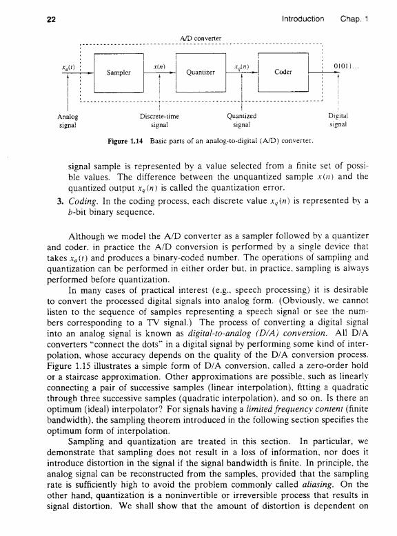
22 Introduction Chap.1 A/D converter xnl tn) 01011.-. Sampler Quantizer Coder Analog Discrete-time Quantized Digital signal signal signal signal Figure 1.14 Basic parts of an analog-to-digital (A/D)converter. signal sample is represented by a value selected from a finite set of possi- ble values.The difference between the unquantized sample x(n)and the quantized output x.(n)is called the quantization error. 3.Coding.In the coding process.each discrete value x(n)is represented by a b-bit binary sequence. Although we model the A/D converter as a sampler followed by a quantizer and coder.in practice the A/D conversion is performed by a single device that takes xe(t)and produces a binary-coded number.The operations of sampling and quantization can be performed in either order but.in practice.sampling is aiways performed before quantization. In many cases of practical interest (e.g..speech processing)it is desirable to convert the processed digital signals into analog form.(Obviously.we cannot listen to the sequence of samples representing a speech signal or see the num- bers corresponding to a TV signal.)The process of converting a digital signal into an analog signal is known as digital-to-analog (D/A)conversion.All D/A converters "connect the dots"in a digital signal by performing some kind of inter- polation,whose accuracy depends on the quality of the D/A conversion process. Figure 1.15 illustrates a simple form of D/A conversion.called a zero-order hold or a staircase approximation.Other approximations are possible.such as linearly connecting a pair of successive samples(linear interpolation).fitting a quadratic through three successive samples (quadratic interpolation).and so on.Is there an optimum (ideal)interpolator?For signals having a limited frequency content(finite bandwidth).the sampling theorem introduced in the following section specifies the optimum form of interpolation. Sampling and quantization are treated in this section.In particular,we demonstrate that sampling does not result in a loss of information.nor does it introduce distortion in the signal if the signal bandwidth is finite.In principle.the analog signal can be reconstructed from the samples.provided that the sampling rate is sufficiently high to avoid the problem commonly called aliasing.On the other hand,quantization is a noninvertible or irreversible process that results in signal distortion.We shall show that the amount of distortion is dependent on
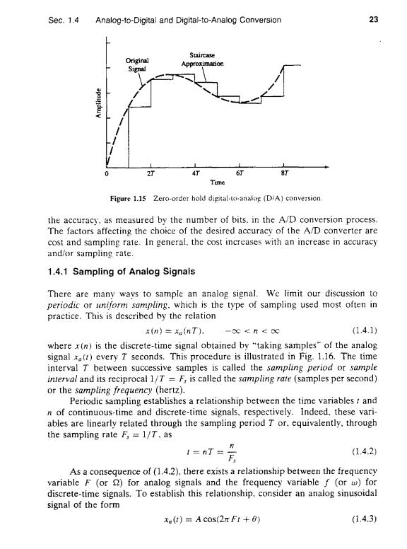
Sec.1.4 Analog-to-Digital and Digital-to-Analog Conversion 23 Stircase Original Approximanon Signal 2T 4T 6T 8T Time Figure 1.15 Zero-order hold digital-to-analog (DiA)conversion. the accuracy.as measured by the number of bits.in the A/D conversion process. The factors affecting the choice of the desired accuracy of the A/D converter are cost and sampling rate.In general.the cost increases with an increase in accuracy and/or sampling rate. 1.4.1 Sampling of Analog Signals There are many ways to sample an analog signal.We limit our discussion to periodic or uniform sampling.which is the type of sampling used most often in practice.This is described by the relation x(n)=x(nT). -00<H<0∝ (1.4.1) where x(n)is the discrete-time signal obtained by "taking samples"of the analog signal x()every T seconds.This procedure is illustrated in Fig.1.16.The time interval T between successive samples is called the sampling period or sample interval and its reciprocal 1/T F;is called the sampling rate (samples per second) or the sampling frequency (hertz). Periodic sampling establishes a relationship between the time variables t and n of continuous-time and discrete-time signals.respectively.Indeed,these vari- ables are linearly related through the sampling period T or.equivalently.through the sampling rate Fs =1/T,as 1=T=片 (1.4.2) As a consequence of(1.4.2),there exists a relationship between the frequency variable F (or for analog signals and the frequency variable f (or w)for discrete-time signals.To establish this relationship,consider an analog sinusoidal signal of the form x(1)=A COS(2 Ft+0) (1.4.3)
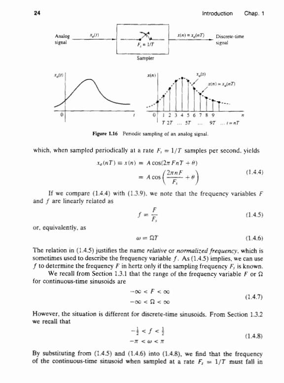
24 Introduction Chap.1 Analog xo(t] )=n) Discrete-time signal F UT signal Sampler 用) xtn 》=n刀 0123456789 T 27...ST..9T ..=nT Figure 116 Penodic sampling of an analog signal. which,when sampled periodically at a rate F.=1/T samples per second.yields xe(nT)=x(n)=Acos(2T FnT+A) (1.4.4 A cos If we compare (1.4.4)with (1.3.9).we note that the frequency variables F and f are linearly related as . (1.4.5) or.equivalently.as 仙=2T (1.4.6) The relation in (1.4.5)justifies the name relative or normalized frequency.which is sometimes used to describe the frequency variable f.As(1.4.5)implies,we can use f to determine the frequency F in hertz only if the sampling frequency F,is known. We recall from Section 1.3.1 that the range of the frequency variable F or for continuous-time sinusoids are -00 F<oo (1.4.7) -00<2<0 However,the situation is different for discrete-time sinusoids.From Section 1.3.2 we recall that -<∫< (1.4.8) 一开<u<开 By substituting from (1.4.5)and (1.4.6)into (1.4.8).we find that the frequency of the continuous-time sinusoid when sampled at a rate F,=1/T must fall in