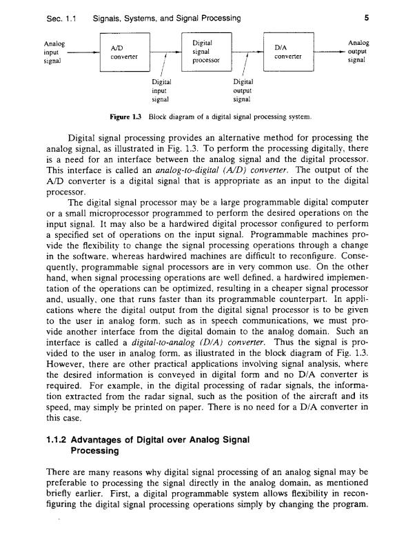
Sec.1.1 Signals,Systems,and Signal Processing 5 Analog Analog A/D Digital D/A input signal output signal converer converter processor signal Digital Digital input output signal signal Figure 1.3 Block diagram of a digital signal processing system. Digital signal processing provides an alternative method for processing the analog signal,as illustrated in Fig.1.3.To perform the processing digitally,there is a need for an interface between the analog signal and the digital processor. This interface is called an analog-to-digital (A/D)converter.The output of the A/D converter is a digital signal that is appropriate as an input to the digital processor. The digital signal processor may be a large programmable digital computer or a small microprocessor programmed to perform the desired operations on the input signal.It may also be a hardwired digital processor configured to perform a specified set of operations on the input signal.Programmable machines pro- vide the flexibility to change the signal processing operations through a change in the software.whereas hardwired machines are difficult to reconfigure.Conse- quently.programmable signal processors are in very common use.On the other hand,when signal processing operations are well defined.a hardwired implemen- tation of the operations can be optimized,resulting in a cheaper signal processor and,usually.one that runs faster than its programmable counterpart.In appli- cations where the digital output from the digital signal processor is to be given to the user in analog form.such as in speech communications,we must pro- vide another interface from the digital domain to the analog domain.Such an interface is called a digital-to-analog (D/A)converter.Thus the signal is pro- vided to the user in analog form.as illustrated in the block diagram of Fig.1.3. However,there are other practical applications involving signal analysis.where the desired information is conveyed in digital form and no D/A converter is required.For example,in the digital processing of radar signals,the informa- tion extracted from the radar signal,such as the position of the aircraft and its speed,may simply be printed on paper.There is no need for a D/A converter in this case. 1.1.2 Advantages of Digital over Analog Signal Processing There are many reasons why digital signal processing of an analog signal may be preferable to processing the signal directly in the analog domain,as mentioned briefty earlier.First,a digital programmable system allows flexibility in recon- figuring the digital signal processing operations simply by changing the program
6 Introduction Chap.1 Reconfiguration of an analog system usually implies a redesign of the hardware followed by testing and verification to see that it operates properly. Accuracy considerations also play an important role in determining the form of the signal processor.Tolerances in analog circuit components make it extremely difficult for the system designer to control the accuracy of an analog signal pro- cessing system.On the other hand.a digital system provides much better control of accuracy requirements.Such requirements.in turn,result in specifying the ac- curacy requirements in the A/D converter and the digital signal processor,in terms of word length,floating-point versus fixed-point arithmetic,and similar factors. Digital signals are easily stored on magnetic media(tape or disk)without de. terioration or loss of signa!fidelity beyond that introduced in the A/D conversion. As a consequence,the signals become transportable and can be processed off-line in a remote laboratory.The digital signai processing method also allows for the im- plementation of more sophisticated signal processing algorithms.It is usually very difficult to perform precise mathematical operations on signals in analog form but these same operations can be routinely implemented on a digital computer using software. In some cases a digital implementation of the signal processing system is cheaper than its analog counterpart.The lower cost may be due to the fact that the digital hardware is cheaper.or perhaps it is a result of the flexibility for mod- ifications provided by the digital implementation. As a consequence of these advantages.digital signal processing has been applied in practical systems covering a broad range of disciplines.We cite,for ex- ample,the application of digital signal processing techniques in speech processing and signal transmission on telephone channels,in image processing and transmis- sion.in seismology and geophysics.in oil exploration.in the detection of nuclear expiosions,in the processing of signals received from outer space.and in a vast variety of other applications.Some of these applications are cited in subsequent chapters. As already indicated.however.digital implementation has its limitations. One practical limitation is the speed of operation of A/D converters and digital signal processors.We shall see that signals having extremely wide bandwidths re- quire fast-sampling-rate A/D converters and fast digital signal processors.Hence there are analog signals with large bandwidths for which a digital processing ap- proach is beyond the state of the art of digital hardware. 1.2 CLASSIFICATION OF SIGNALS The methods we use in processing a signal or in analyzing the response of a system to a signal depend heavily on the characteristic attributes of the specific signal. There are techniques that apply only to specific families of signals.Consequently. any investigation in signal processing should start with a classification of the signals involved in the specific application
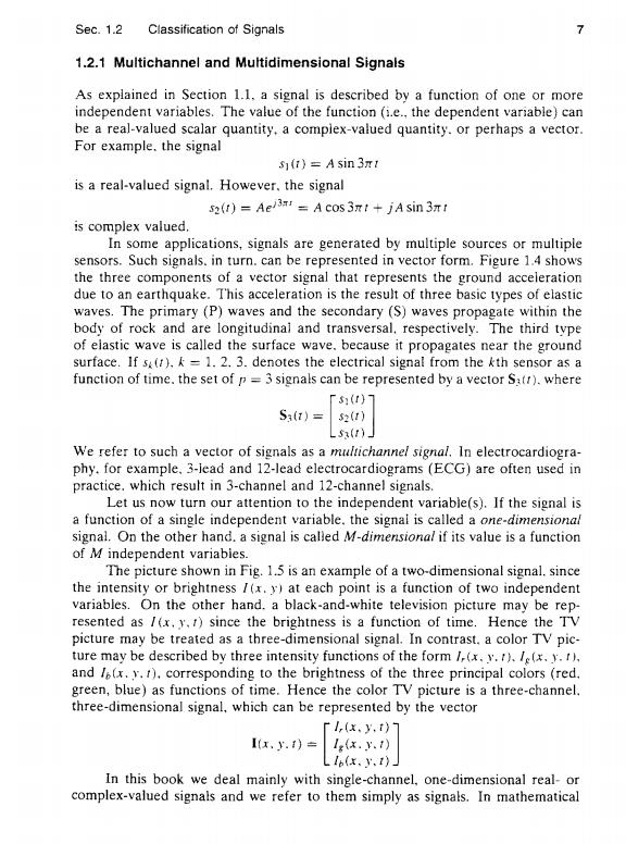
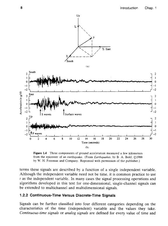
Sec.1.2 Classification of Signals 7 1.2.1 Multichannel and Multidimensional Signals As explained in Section 1.1.a signal is described by a function of one or more independent variables.The value of the function (i.e.,the dependent variable)can be a real-valued scalar quantity.a compiex-valued quantity.or perhaps a vector. For example.the signal s(1)=A sin 3mt is a real-valued signal.However,the signal 52(1)=Ae=A cos3nt jAsin 3t is complex valued. In some applications,signals are generated by multiple sources or multiple sensors.Such signals.in turn.can be represented in vector form.Figure 1.4 shows the three components of a vector signal that represents the ground acceleration due to an earthquake.This acceleration is the result of three basic types of elastic waves.The primary (P)waves and the secondary (S)waves propagate within the body of rock and are longitudinal and transversal.respectively.The third type of elastic wave is called the surface wave.because it propagates near the ground surface.If s().k =1.2.3.denotes the electrical signal from the kth sensor as a function of time.the set of p=3 signals can be represented by a vector S:tr).where 「5()7 S:(t)= 52(1) Lsa(1)_ We refer to such a vector of signals as a multichannel signal.In electrocardiogra- phy.for example,3-lead and 12-lead electrocardiograms (ECG)are often used in practice.which result in 3-channel and 12-channel signals. Let us now turn our attention to the independent variable(s).If the signal is a function of a single independent variable.the signal is called a one-dimensional signal.On the other hand.a signal is called M-dimensional if its value is a function of M independent variabies. The picture shown in Fig.1.5 is an example of a two-dimensional signal.since the intensity or brightness /(x.y)at each point is a function of two independent variables.On the other hand.a black-and-white television picture may be rep- resented as /(x.y.1)since the brightness is a function of time.Hence the TV picture may be treated as a three-dimensional signal.In contrast.a color TV pic- ture may be described by three intensity functions of the form /(x.y.1)./e(x.y.I). and l(x.y.1).corresponding to the brightness of the three principal colors (red. green,blue)as functions of time.Hence the color TV picture is a three-channel. three-dimensional signal.which can be represented by the vector T,(x,y,t》 I,.)= lgx..) L16(x,y.1) In this book we deal mainly with single-channel,one-dimensional real-or complex-valued signals and we refer to them simply as signals.In mathematical
8 Introduction Chap.1 Up Y Y East South (a) South 0 -2 0 -2 Surface waves 2 -1 2 6 10121416182022242628 30 Time (seconds) b Figure 1.4 Three components of ground acceleration measured a few kilometers from the epicenter of an earthquake.(From Earthguakes.by B.A.Bold.1988 by W.H.Freeman and Company.Reprnted with permission of the publisher.) terms these signals are described by a function of a single independent variable. Although the independent variable need not be time.it is common practice to use t as the independent variable.In many cases the signal processing operations and algorithms developed in this text for one-dimensional,single-channel signals can be extended to multichannel and multidimensional signals. 1.2.2 Continuous-Time Versus Discrete-Time Signals Signals can be further classified into four different categories depending on the characteristics of the time (independent)variable and the values they take. Continuous-time signals or analog signals are defined for every value of time and
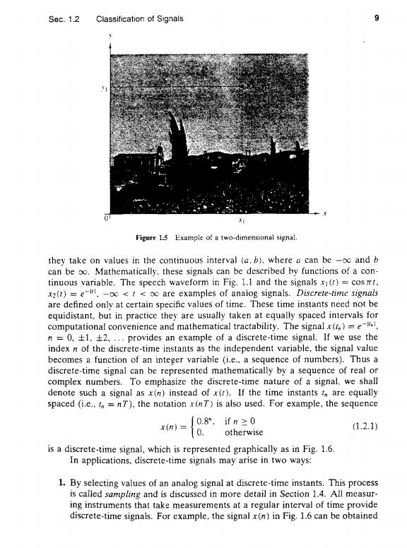
Sec.1.2 Classification of Signals 9 Figure 1.5 Example of a two-dimensional signal. they take on values in the continuous interval (a.b).where a can be -oo and b can be oo.Mathematically.these signals can be described by functions of a con- tinuous variable.The speech waveform in Fig.1.1 and the signals x(t)=cost, x2(1)=e-l,-o<<o are examples of analog signals.Discrete-time signals are defined only at certain specific values of time.These time instants need not be equidistant,but in practice they are usually taken at equally spaced intervals for computational convenience and mathematical tractability.The signal x()=e n=0,±1,±2,,.provides an example of a discrete-time signal,If we use the index n of the discrete-time instants as the independent variable,the signal value becomes a function of an integer variable (i.e..a sequence of numbers).Thus a discrete-time signal can be represented mathematically by a sequence of real or complex numbers.To emphasize the discrete-time nature of a signal,we shall denote such a signal as x(n)instead of x(r).If the time instants i are equally spaced (i.e..=nT),the notation x(nT)is also used.For example,the sequence x(n)= 0.8",ifn≥0 1.2.1) 0. otherwise is a discrete-time signal,which is represented graphically as in Fig.1.6. In applications.discrete-time signals may arise in two ways: 1.By selecting values of an analog signal at discrete-time instants.This process is called sampling and is discussed in more detail in Section 1.4.All measur- ing instruments that take measurements at a regular interval of time provide discrete-time signals.For example,the signal x(n)in Fig.1.6 can be obtained