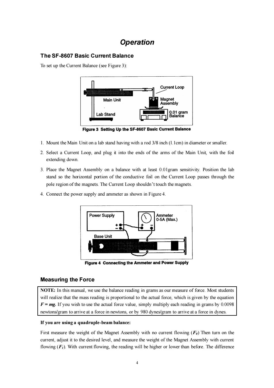
Operation The SF-8607 Basic Current Balance To set up the Current Balance(see Figure 3): Current Loop Main Unit Magnet Assembly Lab Stand 89a8m Flgure 3 Setting Up the SF-8607 Basic Current Balance 1.Mount the Main Unit on a lab stand having with a rod 3/8 inch(1.Icm)in diameter or smaller. 2.Select a Current Loop,and plug it into the ends of the arms of the Main Unit,with the foil extending down. 3.Place the Magnet Assembly on a balance with at least 0.01gram sensitivity.Position the lab stand so the horizontal portion of the conductive foil on the Current Loop passes through the pole region of the magnets.The Current Loop shouldn't touch the magnets. 4.Connect the power supply and ammeter as shown in Figure 4. Power Supply Ammeter 0-5A(Max.) +● Base Unit Flgure 4 Connecting the Ammeter and Power Supply Measuring the Force NOTE:In this manual,we use the balance reading in grams as our measure of force.Most students will realize that the mass reading is proportional to the actual force,which is given by the equation F=mg.If you wish to use the actual force value,simply multiply each reading in grams by 0.0098 newtons/gram to arrive at a force in newtons,or by 980 dynes/gram to arrive at a force in dynes. If you are using a quadruple-beam balance: First measure the weight of the Magnet Assembly with no current flowing(Fo)Then turn on the current,adjust it to the desired level,and measure the weight of the Magnet Assembly with current flowing(F).With current flowing,the reading will be higher or lower than before.The difference
4 Operation The SF-8607 Basic Current Balance To set up the Current Balance (see Figure 3): 1. Mount the Main Unit on a lab stand having with a rod 3/8 inch (l.1cm) in diameter or smaller. 2. Select a Current Loop, and plug it into the ends of the arms of the Main Unit, with the foil extending down. 3. Place the Magnet Assembly on a balance with at least 0.01gram sensitivity. Position the lab stand so the horizontal portion of the conductive foil on the Current Loop passes through the pole region of the magnets. The Current Loop shouldn’t touch the magnets. 4. Connect the power supply and ammeter as shown in Figure 4. Measuring the Force NOTE: In this manual, we use the balance reading in grams as our measure of force. Most students will realize that the mass reading is proportional to the actual force, which is given by the equation F = mg. If you wish to use the actual force value, simply multiply each reading in grams by 0.0098 newtons/gram to arrive at a force in newtons, or by 980 dynes/gram to arrive at a force in dynes. If you are using a quadruple-beam balance: First measure the weight of the Magnet Assembly with no current flowing (F0) Then turn on the current, adjust it to the desired level, and measure the weight of the Magnet Assembly with current flowing (F1). With current flowing, the reading will be higher or lower than before. The difference
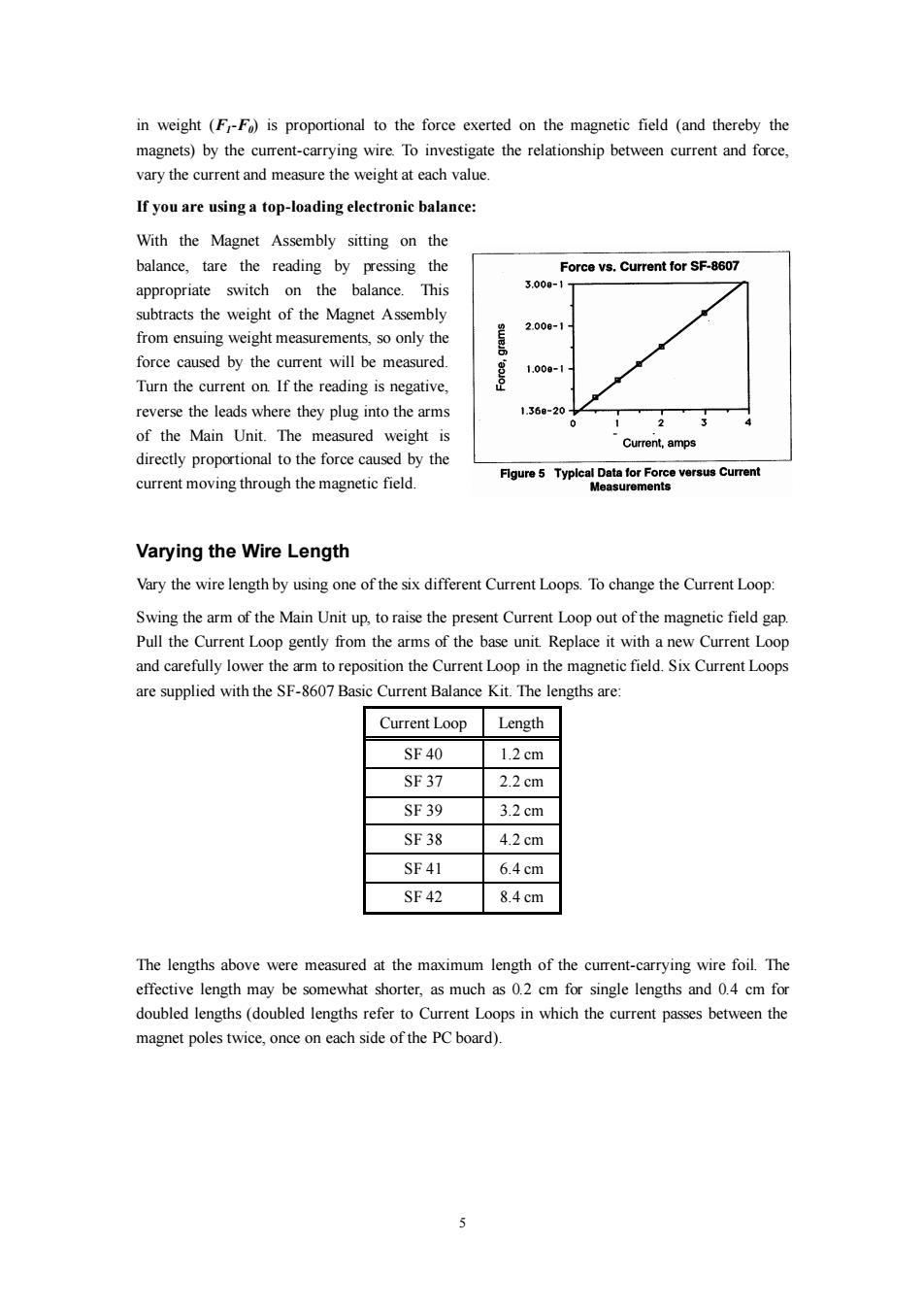
in weight (F-F)is proportional to the force exerted on the magnetic field (and thereby the magnets)by the current-carrying wire.To investigate the relationship between current and force, vary the current and measure the weight at each value. If you are using a top-loading electronic balance: With the Magnet Assembly sitting on the balance,tare the reading by pressing the Force vs.Current for SF-8607 appropriate switch on the balance.This 3.00a-1 subtracts the weight of the Magnet Assembly 2.008-1 from ensuing weight measurements,so only the force caused by the current will be measured. 1.00-1 Turn the current on.If the reading is negative, reverse the leads where they plug into the arms 1.369-201 2 of the Main Unit.The measured weight is Current,amps directly proportional to the force caused by the Figure 5 Typical Data for Force versus Current current moving through the magnetic field. Measurements Varying the Wire Length Vary the wire length by using one of the six different Current Loops.To change the Current Loop: Swing the arm of the Main Unit up,to raise the present Current Loop out of the magnetic field gap. Pull the Current Loop gently from the arms of the base unit.Replace it with a new Current Loop and carefully lower the arm to reposition the Current Loop in the magnetic field.Six Current Loops are supplied with the SF-8607 Basic Current Balance Kit.The lengths are: Current Loop Length SF40 1.2cm SF37 2.2cm SF39 3.2cm SF38 4.2cm SF41 6.4cm SF42 8.4cm The lengths above were measured at the maximum length of the current-carrying wire foil.The effective length may be somewhat shorter,as much as 0.2 cm for single lengths and 0.4 cm for doubled lengths(doubled lengths refer to Current Loops in which the current passes between the magnet poles twice,once on each side of the PC board). J
5 in weight (F1-F0) is proportional to the force exerted on the magnetic field (and thereby the magnets) by the current-carrying wire. To investigate the relationship between current and force, vary the current and measure the weight at each value. If you are using a top-loading electronic balance: With the Magnet Assembly sitting on the balance, tare the reading by pressing the appropriate switch on the balance. This subtracts the weight of the Magnet Assembly from ensuing weight measurements, so only the force caused by the current will be measured. Turn the current on. If the reading is negative, reverse the leads where they plug into the arms of the Main Unit. The measured weight is directly proportional to the force caused by the current moving through the magnetic field. Varying the Wire Length Vary the wire length by using one of the six different Current Loops. To change the Current Loop: Swing the arm of the Main Unit up, to raise the present Current Loop out of the magnetic field gap. Pull the Current Loop gently from the arms of the base unit. Replace it with a new Current Loop and carefully lower the arm to reposition the Current Loop in the magnetic field. Six Current Loops are supplied with the SF-8607 Basic Current Balance Kit. The lengths are: Current Loop Length SF 40 1.2 cm SF 37 2.2 cm SF 39 3.2 cm SF 38 4.2 cm SF 41 6.4 cm SF 42 8.4 cm The lengths above were measured at the maximum length of the current-carrying wire foil. The effective length may be somewhat shorter, as much as 0.2 cm for single lengths and 0.4 cm for doubled lengths (doubled lengths refer to Current Loops in which the current passes between the magnet poles twice, once on each side of the PC board)