
Bright field imaging Topological change of surface generates contrast. Microscope 72 200ym polished etched surface surface groove grain boundary 6
Bright field imaging 6 Topological change of surface generates contrast

Configuration of dark field imaging Tube Lens Oval Mirror Ring Diaphragm Light Source (a) Ring Mirror Oval Mirror Ring Diaphragm Mirror Assembly Ref lected Ring-shaped Light Beam Darkfield Ring Condenser Lens Objective Object ive Lens Concave Specimen Mirror Specimen 7
Configuration of dark field imaging 7
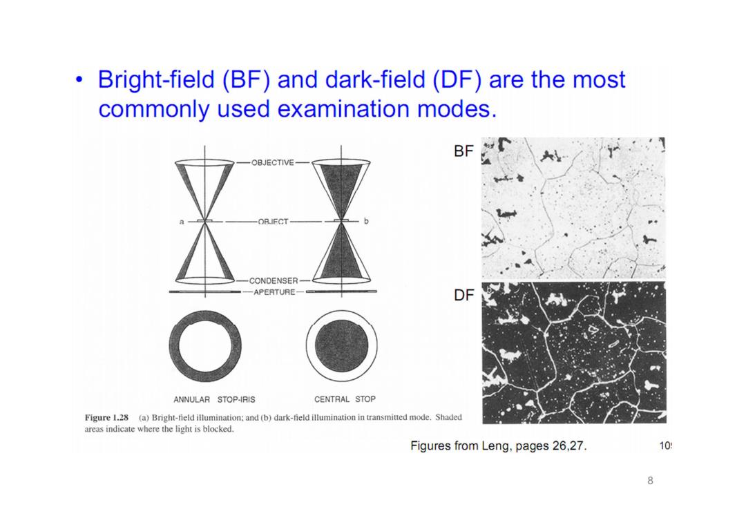
Bright-field(BF)and dark-field(DF)are the most commonly used examination modes. BF OBJECTIVE OBIFCT CONDENSER APERTURE一= DF ANNULAR STOP-IRIS CENTRAL STOP Figure 1.28 (a)Bright-field illumination:and(b)dark-field illumination in transmitted mode.Shaded areas indicate where the light is blocked. Figures from Leng,pages 26,27. 10 8
8

50μm Optical bright field and dark-field metallographic images of a Zircaloy- 4 cladding oxidised in air at 850C(see text section D for signification of regions 1,2,3 and 4) from Nuclear Engineering and Design,Volume 239,Issue 2,February 2009,Pages 244-253 9
9 Optical bright field and dark-field metallographic images of a Zircaloy- 4 cladding oxidised in air at 850 oC (see text section D for signification of regions 1, 2, 3 and 4) from Nuclear Engineering and Design, Volume 239, Issue 2, February 2009, Pages 244–253
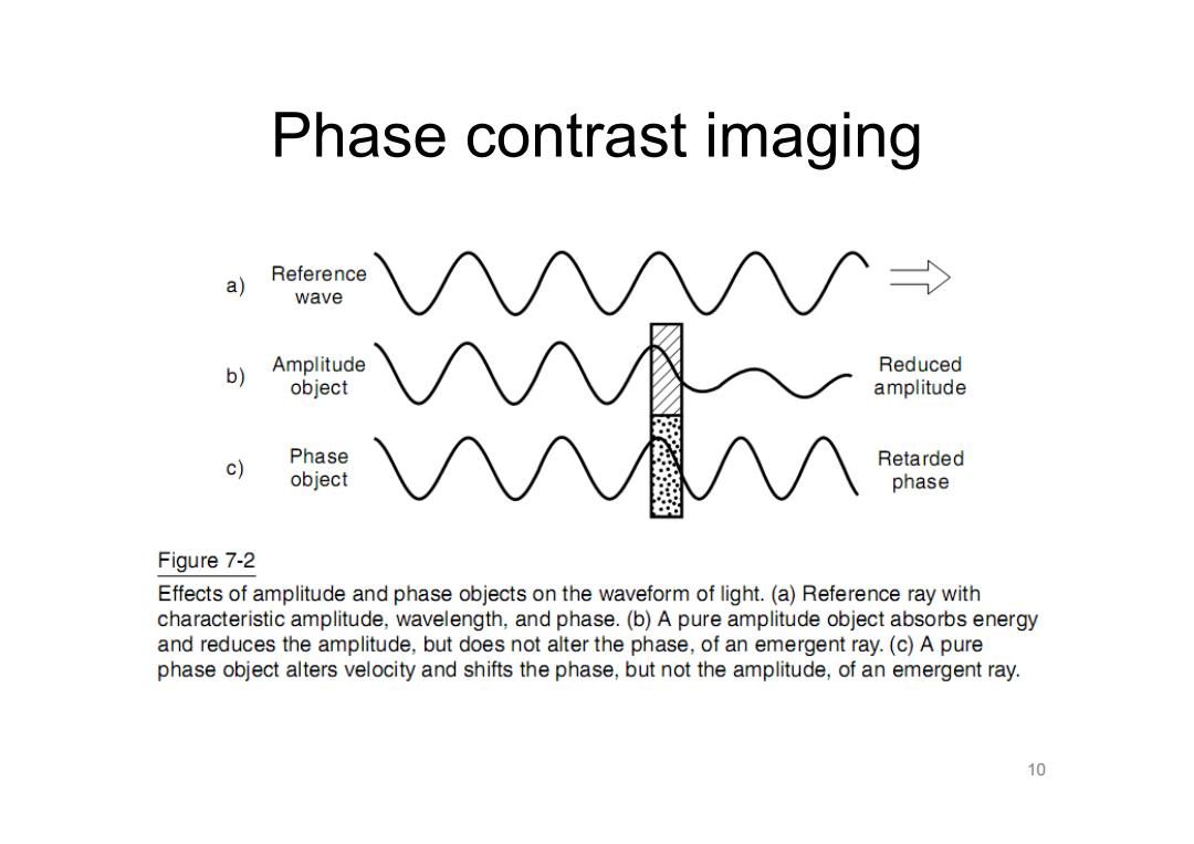
Phase contrast imaging Reference a) wave b) Amplitude Reduced object amplitude c) Phase Retarded object phase Figure 7-2 Effects of amplitude and phase objects on the waveform of light.(a)Reference ray with characteristic amplitude,wavelength,and phase.(b)A pure amplitude object absorbs energy and reduces the amplitude,but does not alter the phase,of an emergent ray.(c)A pure phase object alters velocity and shifts the phase,but not the amplitude,of an emergent ray. 10
Phase contrast imaging 10