386 Mechanics of Materials 2 §10.1 For any given contact load P it is necessary to determine the value of a and b before the maximum contact stress can be evaluated.These are found analytically from equations suggested by Timoshenko and Goodier(29)and adapted by Lipson and Juvinal(21). ie. 「3PA]/3 a=m and b=n 「3PA7/3 4A 4A with △= -+-1 a function of the elastic constants E and v of the contacting bodies and ++后+ A- with R and R'the maximum and minimum radii of curvature of the unloaded contact surfaces in two perpendicular planes. For flat-sided wheels R:will be the wheel radius and R will be infinite.Similarly for railway lines with head radius R2 the value of R2 will be infinite to produce the flat length of rail. 1/2 8=(信)'+(后)+(信-)(信忘)m with the angle between the planes containing curvatures 1/RI and 1/R2. Convex surfaces such as a sphere or roller are taken to be positive curvatures whilst internal surfaces of ball races are considered to be negative. m and n are also functions of the geometry of the contact surfaces and their values are shown in Table 10.1 for various values of the term a cos-(B/A). Table 10.1. 20 3035 40 4550 5560 6570 75 80 85 90 degrees N 3.7782.7312.3972.1361.9261.7541.61114861.3781.2841.2021.1281.0611.000 0.4080.4930.5300.5670.6040.6410.6780.7170.7590.8020.8460.8930.9441000 10.1.2.Special case I-Contact of parallel cylinders Consider the two parallel cylinders shown in Fig.10.3(a)subjected to a contact load P producing a rectangular contact area of width 26 and length L.The contact stress distribution is indicated in Fig.10.3(b). The elliptical pressure distribution is given by the two-dimensional version of eqn (10.1) ie. p= -茶 (10.5) The total load P is then the volume of the prism i.e. P=πbLpo (10.6)
3 86 Mechanics of Materials 2 $10.1 For any given contact load P it is necessary to determine the value of a and b before the maximum contact stress can be evaluated. These are found analytically from equations suggested by Timoshenko and G~odier'~~) and adapted by Lipson and Juvinal(2'). i.e. with 3PA and b = n [=] a function of the elastic constants E and v of the contacting bodies and 11 with R and R' the maximum and minimum radii of curvature of the unloaded contact surfaces in two perpendicular planes. For flat-sided wheels RI will be the wheel radius and R', will be infinite. Similarly for railway lines with head radius R2 the value of R; will be infinite to produce the flat length of rail. with 11/ the angle between the planes containing curvatures l/Rl and 1/R;?. internal surfaces of ball races are considered to be negative. shown in Table 10.1 for various values of the term a = cos-'(B/A). Convex surfaces such as a sphere or roller are taken to be positive curvatures whilst rn and n are also functions of the geometry of the contact surfaces and their values are Table 10.1. a 20 30 35 40 45 50 55 60 65 70 75 80 85 90 degrees m 3.778 2.731 2.397 2.136 1.926 1.754 1.611 1.486 1.378 1.284 1.202 1.128 1.061 1.OOO n 0.408 0.493 0.530 0.567 0.604 0.641 0.678 0.717 0.759 0.802 0.846 0.893 0.944 1.OOO 10.1.2. Special case I - Contact of parallel cylinders Consider the two parallel cylinders shown in Fig. 10.3(a) subjected to a contact load P producing a rectangular contact area of width 26 and length L. The contact stress distribution is indicated in Fig. 10.3(b). The elliptical pressure distribution is given by the two-dimensional version of eqn (10.1) i.e. P = Pq/l - g The total load P is then the volume of the prism i.e. P = inbLpo (10.5) (10.6)

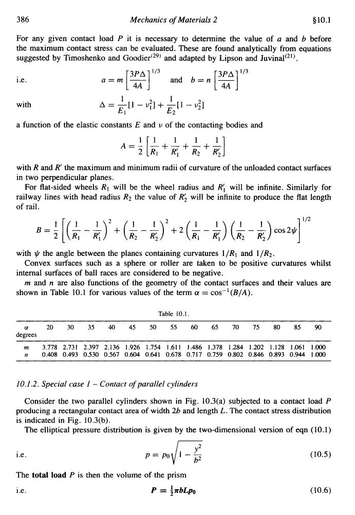
§10.1 Contact Stress,Residual Stress and Stress Concentrations 387 2b P Moximum contoct pressure p (a)Contocting porollel cylinders (b)Pressure (stress)distribution Fig.10.3.(a)Contact of two parallel cylinders;(b)stress distribution for contacting parallel cylinders. and the maximum pressure or maximum compressive stress 2p P0=0c= xbL (10.7) The contact width can be related to the geometry of the contacting surfaces as follows:- P△ b=1.076 (10.8) 】 giving the maximum compressive stress as: P 0c=-p0=-0.5911 R R2 (10.9) LA (For a flat plate R2 is infinite,for a cylinder in a cylindrical bearing R2 is negative). Stress conditions at the surface on the load axis are then: 02=0e=一P0 0y=一p0 ox=-2vpo (along cylinder length) The maximum shear stress is: tmax=0.295p%s0.3p0 occurring at a depth beneath the surface of 0.786 b and on planes at 45 to the load axis. In cases such as gears,bearings,cams,etc.which (as will be discussed later)can be likened to the contact of parallel cylinders,this shear stress will reduce gradually to zero as the rolling load passes the point in question and rise again to its maximum value as the next
$10.1 Contact Stress, Residual Stress and Stress Concentrations (01 Contacting parollel cylinders Maximum contact pressure P, (b) Pressure (stress) distribution 387 Fig. 10.3. (a) Contact of two parallel cylinders: (b) stress distribution for contacting parallel cylinders. and the maximum pressure or maximum compressive stress (10.7) The contact width can be related to the geometry of the contacting surfaces as follows:- (10.8) giving the maximum compressive stress as: 0, = -p~ = -0.591 (10.9) LA (For a flat plate R2 is infinite, for a cylinder in a cylindrical bearing R2 is negative). Stress conditions at the surface on the load axis are then: uy = -Po ax= -2vw (along cylinder length) The maximum shear stress is: occurring at a depth beneath the surface of 0.786 b and on planes at 45" to the load axis. In cases such as gears, bearings, cams, etc. which (as will be discussed later) can be likened to the contact of parallel cylinders, this shear stress will reduce gradually to zero as the rolling load passes the point in question and rise again to its maximum value as the next
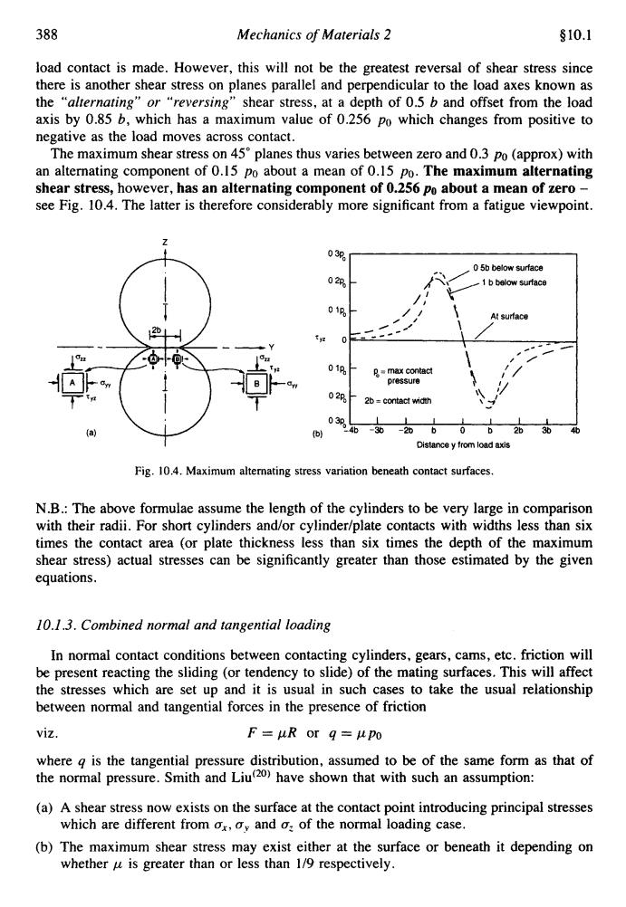
388 Mechanics of Materials 2 §10.1 load contact is made.However,this will not be the greatest reversal of shear stress since there is another shear stress on planes parallel and perpendicular to the load axes known as the "alternating"or "reversing"shear stress,at a depth of 0.5 b and offset from the load axis by 0.85 b,which has a maximum value of 0.256 po which changes from positive to negative as the load moves across contact. The maximum shear stress on 45planes thus varies between zero and 0.3 po (approx)with an alternating component of 0.15 po about a mean of 0.15 Po.The maximum alternating shear stress,however,has an alternating component of 0.256 Po about a mean of zero- see Fig.10.4.The latter is therefore considerably more significant from a fatigue viewpoint. 03p 05b below surface 020 1 b below surface At surface 01p 具=max contact pressure 02 26=contac时wMdh 03p b 46-36-26062b36 46 Distancey from load axis Fig.10.4.Maximum alternating stress variation beneath contact surfaces. N.B.:The above formulae assume the length of the cylinders to be very large in comparison with their radii.For short cylinders and/or cylinder/plate contacts with widths less than six times the contact area (or plate thickness less than six times the depth of the maximum shear stress)actual stresses can be significantly greater than those estimated by the given equations. 10.1.3.Combined normal and tangential loading In normal contact conditions between contacting cylinders,gears,cams,etc.friction will be present reacting the sliding (or tendency to slide)of the mating surfaces.This will affect the stresses which are set up and it is usual in such cases to take the usual relationship between normal and tangential forces in the presence of friction viZ. F=uR or g=upo where g is the tangential pressure distribution,assumed to be of the same form as that of the normal pressure.Smith and Liu20)have shown that with such an assumption: (a)A shear stress now exists on the surface at the contact point introducing principal stresses which are different from ox,oy and o:of the normal loading case. (b)The maximum shear stress may exist either at the surface or beneath it depending on whether u is greater than or less than 1/9 respectively
388 Mechanics oj Materials 2 $10.1 load contact is made. However, this will not be the greatest reversal of shear stress since there is another shear stress on planes parallel and perpendicular to the load axes known as the “alrernating” or “reversing” shear stress, at a depth of 0.5 b and offset from the load axis by 0.85 b, which has a maximum value of 0.256 po which changes from positive to negative as the load moves across contact. The maximum shear stress on 45” planes thus varies between zero and 0.3 po (approx) with an alternating component of 0.15 po about a mean of 0.15 PO. The maximum alternating shear stress, however, has an alternating component of 0.256 po about a mean of zero - see Fig. 10.4. The latter is therefore considerably more significant from a fatigue viewpoint. I Distance y from load axis Fig. 10.4. Maximum alternating stress variation beneath contact surfaces. N.B.: The above formulae assume the length of the cylinders to be very large in comparison with their radii. For short cylinders and/or cylindedplate contacts with widths less than six times the contact area (or plate thickness less than six times the depth of the maximum shear stress) actual stresses can be significantly greater than those estimated by the given equations. 10.1.3. Combined normal and tangential loading In normal contact conditions between contacting cylinders, gears, cams, etc. friction will be present reacting the sliding (or tendency to slide) of the mating surfaces. This will affect the stresses which are set up and it is usual in such cases to take the usual relationship between normal and tangential forces in the presence of friction viz. F=pR or q=ppo where q is the tangential pressure distribution, assumed to be of the same form as that of the normal pressure. Smith and Lid2’) have shown that with such an assumption: (a) A shear stress now exists on the surface at the contact point introducing principal stresses (b) The maximum shear stress may exist either at the surface or beneath it depending on which are different from a,, uy and uz of the normal loading case. whether p is greater than or less than 1/9 respectively
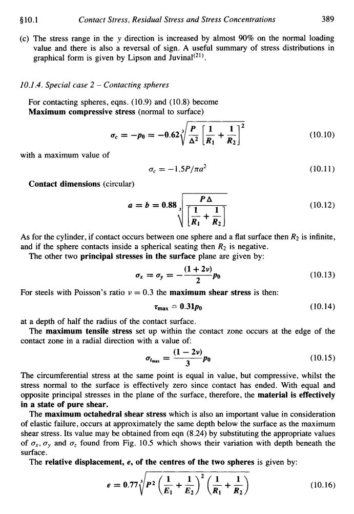
§10.1 Contact Stress,Residual Stress and Stress Concentrations 389 (c)The stress range in the y direction is increased by almost 90%on the normal loading value and there is also a reversal of sign.A useful summary of stress distributions in graphical form is given by Lipson and Juvinal(21). 10.1.4.Special case 2-Contacting spheres For contacting spheres,eqns.(10.9)and (10.8)become Maximum compressive stress (normal to surface) P「1. 172 0c=-p0=-0.621 △2R1 +R2】 (10.10) with a maximum value of Oc =-1.5P/na2 (10.11) Contact dimensions (circular) P△ a=b=0.88 (10.12) 「1 11 As for the cylinder,if contact occurs between one sphere and a flat surface then R2 is infinite, and if the sphere contacts inside a spherical seating then R2 is negative. The other two principal stresses in the surface plane are given by: (1+2) 0x=0y= 2P (10.13) For steels with Poisson's ratio v=0.3 the maximum shear stress is then: tmax±0.31po (10.14) at a depth of half the radius of the contact surface. The maximum tensile stress set up within the contact zone occurs at the edge of the contact zone in a radial direction with a value of: (1-2) Utmax 3P0 (10.15) The circumferential stress at the same point is equal in value,but compressive,whilst the stress normal to the surface is effectively zero since contact has ended.With equal and opposite principal stresses in the plane of the surface,therefore,the material is effectively in a state of pure shear. The maximum octahedral shear stress which is also an important value in consideration of elastic failure,occurs at approximately the same depth below the surface as the maximum shear stress.Its value may be obtained from eqn(8.24)by substituting the appropriate values of ox,oy and o:found from Fig.10.5 which shows their variation with depth beneath the surface. The relative displacement,e,of the centres of the two spheres is given by: e=nP(G+)'(民+》 (10.16)
510.1 Contact Stress, Residual Stress and Stress Concentrations 389 The stress range in the y direction is increased by almost 90% on the normal loading value and there is also a reversal of sign. A useful summary of stress distributions in graphical form is given by Lipson and Juvinal(21). 10.1.4. Special case 2 - Contacting spheres For contacting spheres, eqns. (10.9) and (10.8) become Maximum compressive stress (normal to surface) with a maximum value of a, = - 1.5~lna~ Contact dimensions (circular) a = b = O.8tl3 jE (10.10) (10.11) (10.12) As for the cylinder, if contact occurs between one sphere and a flat surface then R2 is infinite, and if the sphere contacts inside a spherical seating then R2 is negative. The other two principal stresses in the surface plane are given by: (1 + 2u) 2 a, = by = -___ Po (10.13) For steels with Poisson’s ratio v = 0.3 the maximum shear stress is then: tmax 10.31~0 (10.14) The maximum tensile stress set up within the contact zone occurs at the edge of the at a depth of half the radius of the contact surface. contact zone in a radial direction with a value of (1 - 2u) 3 utmax = ___ Po (10.15) The circumferential stress at the same point is equal in value, but compressive, whilst the stress normal to the surface is effectively zero since contact has ended. With equal and opposite principal stresses in the plane of the surface, therefore, the material is effectively in a state of pure shear. The maximum octahedral shear stress which is also an important value in consideration of elastic failure, occurs at approximately the same depth below the surface as the maximum shear stress. Its value may be obtained from eqn (8.24) by substituting the appropriate values of a,, a,, and a, found from Fig. 10.5 which shows their variation with depth beneath the surface. The relative displacement, e, of the centres of the two spheres is given by: e = 0.77 J P2 (i1 - + - iJ2(d+&) (10.16)

390 Mechanics of Materials 2 §10.1 Stress 04 0 04P 2 b.contact semi- Oxis Tu=Ty P。mox.contact pressure Fig.10.5.Variation of stresses beneath the surface of contacting spheres. For a sphere contacting a flat surface of the same material R2=oo and E=E2=E. Substitution in egns.(10.10)and (10.16)then yields maximum compressive stress 0c=-0.62 PE2 4R子 (10.17) and relative displacement of centres P2 e=1.54 2E2R1 (10.18) For a sphere on a spherical seat of the same material 72 oe=-0.62PE2 R2-R (10.19) RR2 P2 R2-R1 with e=1.54 2E2 (10.20) R1R2」 For other,more general,loading cases the reader is referred to a list of formulae presented by Roark and Young(33). 10.1.5.Design considerations It should be evident from the preceding sections that the maximum Hertzian compressive stress is not,in itself,a valid criteria of failure for contacting members although it can be used as a valid design guide provided that more critical stress states which have a more direct influence on failure can be related directly to it.It has been shown,for example,that alternating shear stresses exist beneath the surface which are probably critical to fatigue life
390 Mechanics of Materials 2 Stress $10.1 Fig. 10.5. Variation of stresses beneath the surface of contacting spheres. For a sphere contacting a flat surj-ace of the same material R2 = 00 and El = E2 = E. Substitution in eqns. (10.10) and (10.16) then yields maximum compressive stress U, = -0.62’ - /:; (10.17) and relative displacement of centres For a sphere on a spherical seat of the same material (10.18) ( 10.19) with (10.20) For other, more general, loading cases the reader is referred to a list of formuIae presented by Roark and Young(33). 10.1.5. Design considerations It should be evident from the preceding sections that the maximum Hertzian compressive stress is not, in itself, a valid criteria of failure for contacting members although it can be used as a valid design guide provided that more critical stress states which have a more direct influence on failure can be related directly to it. It has been shown, for example, that alternating shear stresses exist beneath the surface which are probably critical to fatigue life