2013-4-19 Words and Expressions 园 Light frame wood constructions Dm隔板 Prof.He Minjuan diaphragm Tongii University.Shanghai China shear wall Words and Expressions Outline nchorage周 rafter 1.General concepts )2.Desin principles 3.Design of light frame diaphragn 4.Design of shear wall 5.Case study hold-down .General concepts 1.General concepts Flat or curved plate type elements that transmit forces i their plane Shear wall 1
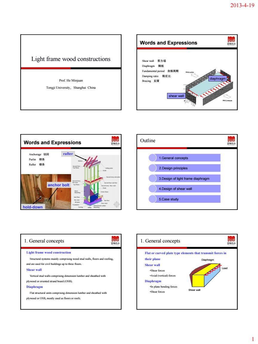
2013-4-19 1 Light frame wood constructions Prof. He Minjuan Tongji University, Shanghai China Words and Expressions Shear wall 剪力墙 Diaphragm 隔板 Fundamental period 自振周期 Damping ratio 阻尼比 Bracing 支撑 diaphragm shear wall Words and Expressions Anchorage 锚固 Purlin 檩条 Rafter 椽条 hold-down anchor bolt rafter Outline 1.General concepts 2.Design principles 3.Design of light frame diaphragm 4.Design of shear wall 5.Case study 1. General concepts Light frame wood construction Structural systems mainly comprising wood stud walls, floors and roofing, and are used for civil buildings up to three floors. Shear wall Vertical stud walls comprising dimension lumber and sheathed with plywood or oriented strand board (OSB). Diaphragm Flat structural units comprising dimension lumber and sheathed with plywood or OSB, mostly used as floors or roofs. 1. General concepts Flat or curved plate type elements that transmit forces in their plane Shear wall •Shear forces •Axial (vertical) forces Diaphragm •In plane bending forces •Shear forces Diaphragm Shear wall Load
2013-4-19 1.General concepts 1.General concepts Typical Shear walls and Dis Configuration of wood shear wall 1.General concepts 2.Design principles Load path Load 001. 2.Design principles 2.Design principles Material Design principles ged与yh 2
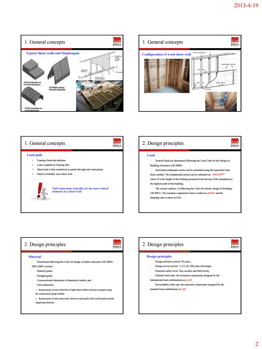
2013-4-19 2 1. General concepts Typical Shear walls and Diaphragms 1. General concepts Configuration of wood shear wall 1. General concepts Nail connections typically are the most critical elements in a shear wall. Load path • Framing forms the skeleton • Load is applied to framing first • Shear load is then transferred to panels through nail connections • Panels eventually carry shear load 2. Design principles Load • General loads are determined following the Load Code for the Design of Building Structures GB 50009; • Horizontal earthquake action can be calculated using the equivalent base shear method. The fundamental period can be estimated as: T=0.05H0.75 where H is the height of the building measured from the top of the foundation to the highest point of the building. • The seismic analysis is following the Code for seismic design of buildings GB 50011. The resistance adjustment factor is taken as γ=0.80 and the damping ratio is taken as 0.05. 2. Design principles Material • Determined following the Code for design of timber structures GB 50005- 2003 (2005 version) • Material grade; • Strength grade; • Cross-sectional dimension of dimension lumber; and • Nail connection: 1. Requirements of nail connection of light frame timber structures designed using the construction design method. 2. Requirements of nail connections between wall panels, floor (roof) panels and the supporting elements. 2. Design principles Design principles • Design reference period: 50 years; • Design service period: 5, 25, 50, 100 years and longer; • Structural safety level: first, second, and third levels; • Ultimate limit state: the structural components designed by the fundamental load combinations as λ0S≤R • Serviceability limit sate: the structural components designed by the standard load combinations as S≤R
2013-4-19 2.Design principles 园 2.Design principles 园 Load carrying systems 2.Design principles 2.Design principles Design indices rage and bracing to 2.Design principles 2.Design principles Maximam allowable yalues Fable I Max s ratos of comp Types of membe No. 120 20 150 150 330 3
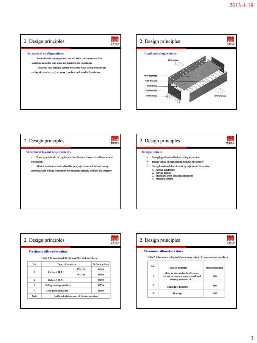
2013-4-19 3 2. Design principles Structural configurations • Vertical load carrying system: vertical loads (permanent and live loads) are passed to wall studs and further to the foundation. • Horizontal load carrying system: horizontal loads (wind pressure and earthquake actions, etc.) are passed to shear walls and to foundation. 2. Design principles Load carrying systems 2. Design principles Structural layout requirements • Plane layout should be regular; the distribution of mass and stiffness should be uniform. • All structural components should be properly connected with necessary anchorage and bracing to maintain the structural strength, stiffness and integrity. 2. Design principles Design indices • Strength grades classified according to species • Design values of strength and modulus of elasticity • Strength and modulus of elasticity adjustment factors for: 1. Service conditions; 2. Service period; 3. Shape and cross-sectional dimension 4. Moisture content 2. Design principles Maximum allowable values No. Types of members Deflection limit 1 Purlins(檩条) l≤3.3 m l>3.3 m 1/200 1/250 2 Rafters(椽条) 1/150 3 Ceiling bending members 1/250 4 Floor girder and joints 1/250 Note l is the calculation span of flexural members Table 1 Maximum deflection of flexural members 2. Design principles Table2 Maximum values of slenderness ratios of compression members No. Types of members Slenderness limit 1 Main members (chords of trusses, vertical members at supports and load carrying columns, etc.) 120 2 Secondary members 150 3 Bracings 200 Maximum allowable values

2013-4-19 2.Design principles 2.Design principles Design methods Basic requiremets for cntruction design methed 36 2.Design principles 3.Design of wood diaphragm mum length of shear wall HHHHHHHHHHHHHHHHHH 十TENSION 3.Design of wood diaphragm 3.Design of wood diaphragm Shear resistance Shear resistance 4
2013-4-19 4 2. Design principles Design methods • Vertical loads: use the general structural analysis and design methods • Horizontal loads: 1. Meeting the detailing requirements: use the construction design method based on performance history; 2. Not meeting the detailing requirements: design based on the shear resistance of floor (roof) diaphragms and shear walls (Engineering calculated design). Basic requirements for construction design method • Building geometry: 1. Floor area less than 600m2,story height no more than 3.6m. 2. Roof slope no less than 1:12 and no bigger than 1:1. 3. Cornice overhanging length on longitudinal walls no more than 1.2m 4. Cornice overhanging length on transverse walls no more than 0.4m • Seismic fortification intensity: 5. Height-to-width ratio of the buildings designed with a seismic fortification intensity of 6 or 7 should not be more than 1.2. 6. Height-to-width ratio of the buildings designed with a seismic fortification intensity of 7 or 8 (0.2g) should not be more than 1.0. 2. Design principles 2. Design principles Minimum length of shear wall The following requirements should be met based on the seismic fortification intensity and the basic wind pressure. 按构造要求设计时剪力墙的最小长度 基本风压( 2 kN / m ) 每到剪力墙的最小长度 地面粗糙度 单层、二层 或三层的顶层 二层的底层 三层的二层 三层的底层 抗震 设防 烈度 A B C D 剪力墙 最大间 距(m) 最 大 允 许 层 数 木基结构 板材面板 石膏板 面板 木基结构 板材面板 石膏板 面板 木基结构 板材面板 石膏板 面板 6 - - 0.30 0.40 0.50 7.6 3 0.25L 0.50 L 0.40 L 0.75 L 0.55 L - 0.10g - 0.35 0.50 0.60 7.6 3 0.30 L 0.60 L* 0.45 L 0.90 L* 0.70 L - 7 0.15g 0.35 0.45 0.60 0.70 5.3 3 0.30 L 0.60 L* 0.45 L 0.90 L* 0.70 L - 8 0.20g 0.40 0.55 0.75 0.80 5.3 2 0.45 L 0.90 L 0.70 L - - - 注:1 建筑物长度 L 指平行于该剪力墙方向的建筑物长度; 2 当墙体用石膏板作面板时,墙体两侧均应采用;当墙体用木基结构板材作面板时,至少墙体一侧采用; 3 位于基础顶面和底层之间的架空层剪力墙的最小长度与底层要求相同; 4 “*”号表示当楼面有混凝土面层时,面板不允许采用石膏版; 5 所有外墙均应采用木基结构板作面板;当建筑物为三层、平面长宽比大于 2.5:1 时,所有横墙的面板应 采用两面木基结构板;当建筑物为二层、平面长宽比大于 2.5:1 时,至少横墙的面板应采用两面木基结构板; 6 采用木基结构板材的剪力墙最大间距:抗震设防烈度为 6 度、7 度(0.10g)时,不得大于 10.6m;抗震设 防烈度为 7 度(0.15g)、8 度(0.20g)时,不得大于 7.6m。 3. Design of wood diaphragm TENSION COMPRESSION SHEAR Floor and roof 3. Design of wood diaphragm Shear resistance • Dimension requirement: the length to width ratio for each unit is less than 4:1. • Design assumption: lateral load is uniformly distributed along the width of the floor and roof diaphragms. 3. Design of wood diaphragm Shear resistance • Design value of shear resistance can be calculated as V=fd ∙B fd=f vd∙k1 ∙k2 where B: effective diaphragm width in parallel to the load direction (m) k1 : moisture content adjustment factor for wood based panel products for M.C.<16% k1 =1.0 for 16%<M.C.<20% k1 =0.75 k2 : wood specie adjustment factor framing members Douglas fir, larch and southern pine k2 =1.0 Hemlock and Hem-fir k2 =0.9 Spruce-pine-fir k2 =0.8 Other N.A. species k2 =0.7 f vd: Design value of shear resistance of floor and roof diaphragms using wood based panel products (kN/m)
2013-4-19 3.Design of wood diaphragm 3.Design of wood diaphragm 1表中数值用于打适接的木基板材的性,屋面板。在干使用条件下,都发 8 21 28 3.Design of wood diaphragm 园 3.Design of wood diaphragm 园 Types ofshear wall Boundary membe 3.Design of wood diaphragm 购 4.Design of wood shear wall 园 Boundary members Faiture modes 5
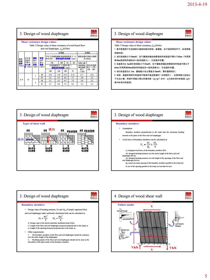
2013-4-19 5 3. Design of wood diaphragm Shear resistance design values Table 3 Design value of shear resistance of wood based floor and roof diaphragm, f vd (kN/m) 普通 圆钉 直径 (mm) 钉在骨 架构件 中最小 打入深 度(mm) 面板 最小 名义 厚度 (mm) 骨架 构件 最小 宽度 (mm) 有填块 无填块 平行于荷载的面板边连续的情况下(3 型和4型),面板边缘钉的间距(mm) 面板边缘钉的最大间距 为150mm 150 100 65 50 荷载与面 板连续边 垂直的情 况下 (1型) 所有其他情 况下(2型、 3型、4型) 在其他情况下(1型和2型), 面板边钉的间距(mm) 150 150 100 75 2.8 31 7 40 3.0 4.0 6.0 6.8 2.7 2.0 65 3.4 4.5 6.8 7.7 3.0 2.2 9 40 3.3 4.5 6.7 7.5 3.0 2.2 65 3.7 5.0 7.5 8.5 3.3 2.5 3. Design of wood diaphragm Table 3 Design value of shear resistance, f vd (kN/m) 1 表中数值用于钉连接的木基结构板材的楼、屋面板,在干燥使用条件下,标准荷载 持续时间; 2 当钉的间距小于50mm时,位于面板拼缝处的骨架构件的宽度不得小于65mm(可用两 根40mm宽的构件组合在一起传递剪力),钉应错开布置; 3 当直径为3.7mm的钉的间距小于75mm时,位于面板拼缝处的骨架构件宽度不得小于 65mm(可用两根40mm宽的构件组合在一起传递剪力),钉应错开布置; 4 当钉的直径为3.7mm,面板最小名义厚度为18mm时,需布置两排钉; 5 当楼、屋盖所用的钉的直径不是表中规定数值时(采用射钉),抗剪承载力应按以 下方法计算:将表中承载力乘以折算系数 (d1/d2) 2,式中,d1为非标准钉的直径,d2为 表中标准钉的直径。 Shear resistance design values 3. Design of wood diaphragm 纵向 横向 Types of shear wall 3. Design of wood diaphragm Boundary members • Assumption Boundary members perpendicular to the loads take the maximum bending moment in the plane of the floor and roof diaphragm. • Axial force of boundary members can be calculated as Nr : designed axial force of the boundary members (kN) M1 : designed bending moment over the entire length of the floor and roof diaphragm (kN.m) M2 : designed bending moment over the length of the openings of the floor and roof diaphragm (kN.m) B0 : center-on-center spacing of the boundary members parallel to the loads (m) b: size of the opening parallel to the loads, no less than 0.6 (m) b M B M Nr 2 0 1 3. Design of wood diaphragm Boundary members • Design value of bending moment, M1 and M2 , of simply supported floor and roof diaphragm under uniformly distributed load can be calculated as w: Design value of the lateral uniformly distributed load, kN/m. L: Length of the floor and roof diaphragm measured perpendicular to the loads, m a: Length of the opening measured perpendicular to the loads, m. • Other requirements 1. The boundary members of the floor and roof diaphragms should be continues over the entire length of the diaphragms. 2. Sheathing panels of the floor and roof diaphragms should not be used as the side plates of the splice joints of the boundary members. 8 2 1 WL M 8 2 2 Wa M 4. Design of wood shear wall h b V Vh/b Vh/b V Failure modes