第6卷第1期 智能系统学报 Vol.6 No.1 2011年2月 CAAI Transactions on Intelligent Systems Feh.2011 doi:10.3969/j.iasn.1673-4785.2011.01.012 Fuzzy logic for large mining bucket wheel reclaimer motion control-from an engineer's perspective LU Tienfu (School of Mechanical Engineering,University of Adelaide,North Terrace Adelaide,South Australia SA 5005,Australia) Abstract:The bucket wheel reclaimer(BWR)is a key piece of equipment which has been widely used for stacking and reclai- ming bulk materials (i.e.iron ore and coal)in places such as ports,iron-steel plants,coal storage areas,and power stations from stockpiles.BWRs are very large in size,heavy in weight,expensive in price,and slow in motion.There are many challen- ges in attempting to automatically control their motion to accurately follow the required trajectories involving uncertain parameters from factors such as friction,turbulent wind,its own dynamics,and encoder limitations.As BWRs are always heavily engaged in production and cannot be spared very long for motion control studies and associated developments,a BWR model and simulation environment closely resembling real life conditions would be beneficial.The following research focused mainly on the implementa- tion of fuzzy logic to a BWR motion control from an engineer's perspective.First,the modeling of a BWR including partially known parameters such as friction force and turbulence to the system was presented.This was then followed by the design of a fuzzy logic-based control built on a model-based control loop.The investigation provides engineers with an example of applying fuzzy logic in a model based approach to properly control the motion of a large BWR following defined trajectories,as well as to show possible ways of further improving the controller performance.The result indicates that fuzzy logic can be applied easily by engineers to overcome most motion control issues involving a large BWR. Keywords:bucket wheel reclaimer;modeling;simulation;motion control;fuzzy logic CLC Number:TP273.4 Document code:A Article ID:1673-4785(2011)01-0085-10 The Australian mineral industry has played an im- issues which have arisen due to the uncertainties portant role in Australia's economy for years.A snap-caused by the insufficient knowledge and modeling er- shot shows that it represented 26%of Australian cap- rors of the bucket wheel reclaimer (BWR)that are ital investment,8%of total national GDP,and 40% normally associated with stacking and reclaiming stock- of total trade in the 2006-2007 fiscal year.The in- pilesin port areas. dustry is mostly located in rural and remote Australia, Anyone who knows the field would agree that and contributes vast sums to the taxation and royalty there are a lot more areas regarding the operations asso- revenues of the Australian Governments. ciated with BWRs which could be further developed, The mining industry is one of the most important including improving the efficiency of BWR motion con- export industries in Australia.Mining covers a broad trol.Nevertheless,stockpiles and BWRs within a spectrum of activities,from exploring and identifying stockyard are always heavily engaged and stretched to new ore bodies such as coal,to processing,transporta- production limits.As they often cannot be spared for tion,and exporting.Before solid bulk materials such the required time period of research and development as metal ores are exported,they are normally stock- in order to improve operation efficiencies,alternatives piled at ports while waiting to be reclaimed according are required.One of the choices is simulation.By to the desired quality and quantity combinations,and properly reflecting the physics in areas such as uncer- subsequently loaded to ships. tainty in computer simulation environments,research The presented work concerns the motion control and development can be carried out without interrup- Received Date:2010-09-25. ting the production operation of real BWRs until the Corresponding Author:LU Tienfu.E-mail:tien-fu.luadelaide.edu.u very late stages involving fine tuning and implementa- tions
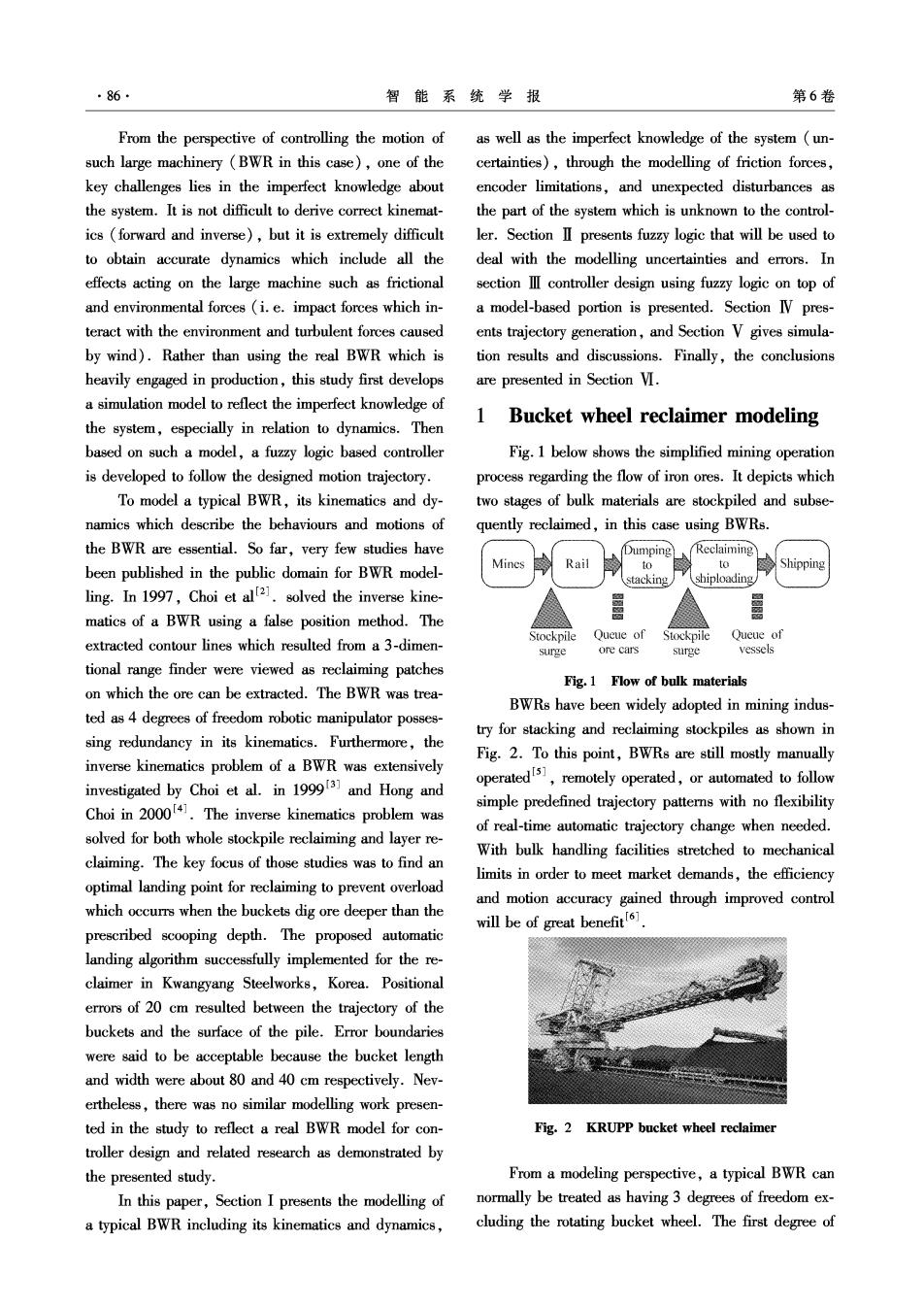
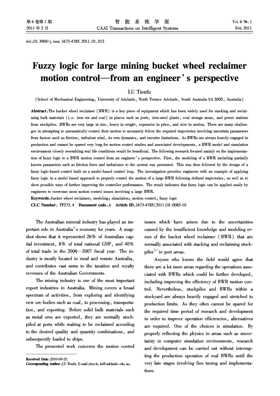
86 智能系统学报 第6卷 From the perspective of controlling the motion of as well as the imperfect knowledge of the system (un- such large machinery (BWR in this case),one of the certainties),through the modelling of friction forces, key challenges lies in the imperfect knowledge about encoder limitations,and unexpected disturbances as the system.It is not difficult to derive correct kinemat- the part of the system which is unknown to the control- ics (forward and inverse),but it is extremely difficult ler.Section II presents fuzzy logic that will be used to to obtain accurate dynamics which include all the deal with the modelling uncertainties and errors.In effects acting on the large machine such as frictional section II controller design using fuzzy logic on top of and environmental forces (i.e.impact forces which in- a model-based portion is presented.Section IV pres- teract with the environment and turbulent forces caused ents trajectory generation,and Section V gives simula- by wind).Rather than using the real BWR which is tion results and discussions.Finally,the conclusions heavily engaged in production,this study first develops are presented in Section VI. a simulation model to reflect the imperfect knowledge of 1 Bucket wheel reclaimer modeling the system,especially in relation to dynamics.Then based on such a model,a fuzzy logic based controller Fig.1 below shows the simplified mining operation is developed to follow the designed motion trajectory. process regarding the flow of iron ores.It depicts which To model a typical BWR,its kinematics and dy- two stages of bulk materials are stockpiled and subse- namics which describe the behaviours and motions of quently reclaimed,in this case using BWRs. the BWR are essential.So far,very few studies have Dumping Reclaiming been published in the public domain for BWR model- Rail to to Shipping stacking shiploading/ ling.In 1997,Choi et alt2.solved the inverse kine- matics of a BWR using a false position method.The extracted contour lines which resulted from a 3-dimen- Stockpile Queue of Stockpile Queue of surge ore cars surge vessels tional range finder were viewed as reclaiming patches Fig.1 Flow of bulk materials on which the ore can be extracted.The BWR was trea- BWRs have been widely adopted in mining indus- ted as 4 degrees of freedom robotic manipulator posses- try for stacking and reclaiming stockpiles as shown in sing redundancy in its kinematics.Furthermore,the Fig.2.To this point,BWRs are still mostly manually inverse kinematics problem of a BWR was extensively investigated by Choi et al.in 199913 and Hong and operatedis,remotely operated,orautomted to follow Choi in 2000141.The inverse kinematics problem was simple predefined trajectory patterns with no flexibility of real-time automatic trajectory change when needed. solved for both whole stockpile reclaiming and layer re- With bulk handling facilities stretched to mechanical claiming.The key focus of those studies was to find an limits in order to meet market demands,the efficiency optimal landing point for reclaiming to prevent overload and motion accuracy gained through improved control which occurrs when the buckets dig ore deeper than the will be of great benefit1. prescribed scooping depth.The proposed automatic landing algorithm successfully implemented for the re- claimer in Kwangyang Steelworks,Korea.Positional errors of 20 cm resulted between the trajectory of the buckets and the surface of the pile.Error boundaries were said to be acceptable because the bucket length and width were about 80 and 40 cm respectively.Nev- ertheless,there was no similar modelling work presen- ted in the study to reflect a real BWR model for con- Fig.2 KRUPP bucket wheel reclaimer troller design and related research as demonstrated by the presented study. From a modeling perspective,a typical BWR can In this paper,Section I presents the modelling of normally be treated as having 3 degrees of freedom ex- a typical BWR including its kinematics and dynamics, cluding the rotating bucket wheel.The first degree of
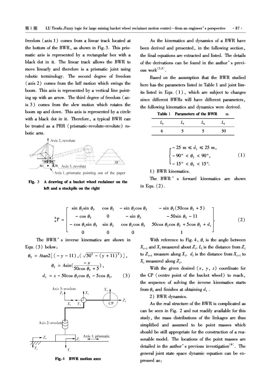
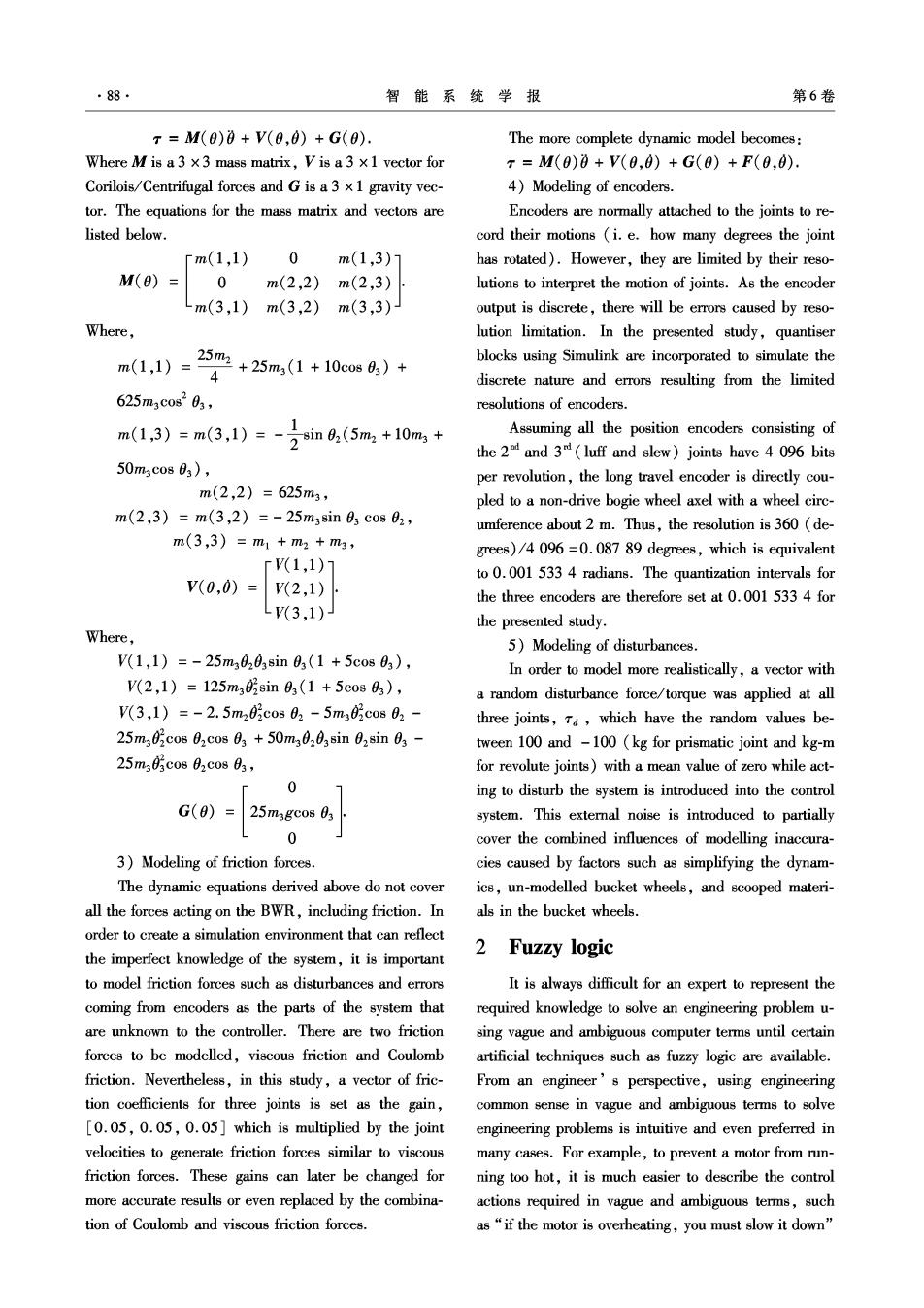
第1期LU Tienfu:Fuz☒logic for large mining bucket wheel reclaimer motion contro--from an engineer's perspective·87· freedom (axis 1)comes from a linear track located at As the kinematics and dynamics of a BWR have the bottom of the BWR,as shown in Fig.3.This pris- been derived and presented,in the following section, matic axis is represented by a rectangular box with a the final equations are extracted and listed.The details black dot in it.The linear track allows the BWR to of the derivations can be found in the author's previ- move linearly and therefore is a prismatic joint using ous work[3.5] robotic terminology.The second degree of freedom Based on the assumption that the BWR studied (axis 2)comes from the luff motion which swings the here has the parameters listed in Table 1 and joint lim- boom.This axis is represented by a vertical line point- its listed in Equ.(1),which are subject to changes ing up with an arrow.The third degree of freedom (ax- since different BWRs will have different parameters, is 3)comes from the slew motion which rotates the the following kinematics and dynamics were derived. boom up and down.This axis is represented by a circle Table 1 Parameters of the BWR with a black dot in it.Therefore,a typical BWR can L L be treated as a PRR (prismatic-revolute-revolute)ro- botic arm. 6 5 5 50 ↑Axis2,revolute r-25m≤d1≤25m, -90°<02<90°, (1) Axis 3,revolute l-15°<03<15°, Axis 1,prismatic pointing out of the paper 1)BWR kinematics. The BWR's forward kinematics are shown Fig.3 A drawing of a bucket wheel reclaimer on the left and a stockpile on the right in Equ.(2). sin 02sin 0 cos 02 sin 02cos 0 -8in02(50cos03+5) T -C0883 0 -sin 03 -50sin03-11 (2) cos 0,sin 0 sin 0, c0802c0803 50cos 02cos 03 +5cos 02+d 0 0 0 1 The BWR's inverse kinematics are shown in With reference to Fig.4,0;is the angle between Equ.(3)below: X-I and X;measured about ZL;is the distance from Z 6,=Aan2[(-y-11),(√502-(y+11))], to Z measure along Xd is the distance from X to &=4sin(50eni6+5, X:measured along Z:. With the given desired (x,y,z)coordinate for d1=z-50cos02c0803-5cos02: (3) the CP (centre point of the bucket wheel)to reach, the sequence of solving the inverse kinematics starts Axis 3:revolute from 03 and finishes at obtaining d. Z. X 2)BWR dynamics. CP As the real structure of the BWR is complicated as can be seen in Fig.2 and not readily available for this study,the mass distributions of the linkages are thus Axis 2:revolute simplified and assumed to be point masses which should be still appropriate for the construction of a rea- Axis 1:prismatic sonable model.The locations of the point masses are detailed in the author's previous investigation.The general joint state space dynamic equation can be ex- Fig.4 BWR motion axes pressed as:
·88· 智能系统学报 第6卷 x=M(0)0+V(0,0)+G(0). The more complete dynamic model becomes: Where M is a 3 x3 mass matrix,V is a 3 x 1 vector for r=M(0)0+V0,0)+G(0)+F(0,0). Corilois/Centrifugal forces and G is a 3 x1 gravity vec- 4)Modeling of encoders. tor.The equations for the mass matrix and vectors are Encoders are normally attached to the joints to re- listed below. cord their motions (i.e.how many degrees the joint rm(1,1) 0 m(1,3)1 has rotated).However,they are limited by their reso- M(0)= 0m(2,2)m(2,3) lutions to interpret the motion of joints.As the encoder m(3,1)m(3,2)m(3,3) output is discrete,there will be errors caused by reso- Wher lution limitation.In the presented study,quantiser m(1,1)-250+25m(1+10cos64)+ blocks using Simulink are incorporated to simulate the discrete nature and errors resulting from the limited 625m3cos203, resolutions of encoders. m1,3》=m(3,1)=ia,(5m+10%,+ Assuming all the position encoders consisting of the 2 4 and 3(luff and slew)joints have 4 096 bits 50m3c0s03), per revolution,the long travel encoder is directly cou- m(2,2)=625m3, pled to a non-drive bogie wheel axel with a wheel circ- m(2,3)=m(3,2)=-25m3sin03cos02, umference about 2 m.Thus,the resolution is 360 (de- m(3,3)=m1+m2+m3, grees)/4096=0.087 89 degrees,which is equivalent r(1,1)7 to 0.001 533 4 radians.The quantization intervals for V(0,0)= (2,1) the three encoders are therefore set at 0.001 533 4 for LV(3,1) the presented study. Where, 5)Modeling of disturbances. V(1,1)=-25m30203sin03(1+5cos03), In order to model more realistically,a vector with V(2,1)=125m35sin03(1+5cos03), a random disturbance force/torque was applied at all V(3,1)=-2.5m25cos02-5m3cos02- three joints,Ta,which have the random values be- 25m305co802cos03+50m30203sin028in03- tween 100 and -100(kg for prismatic joint and kg-m 25m33c0802c0s03, for revolute joints)with a mean value of zero while act- 0 ing to disturb the system is introduced into the control G(0)= 25magcos 03 system.This external noise is introduced to partially 0 cover the combined influences of modelling inaccura- 3)Modeling of friction forces. cies caused by factors such as simplifying the dynam- The dynamic equations derived above do not cover ics,un-modelled bucket wheels,and scooped materi- all the forces acting on the BWR,including friction.In als in the bucket wheels. order to create a simulation environment that can reflect the imperfect knowledge of the system,it is important 2 Fuzzy logic to model friction forces such as disturbances and errors It is always difficult for an expert to represent the coming from encoders as the parts of the system that required knowledge to solve an engineering problem u- are unknown to the controller.There are two friction sing vague and ambiguous computer terms until certain forces to be modelled,viscous friction and Coulomb artificial techniques such as fuzzy logic are available. friction.Nevertheless,in this study,a vector of fric- From an engineer's perspective,using engineering tion coefficients for three joints is set as the gain, common sense in vague and ambiguous terms to solve [0.05,0.05,0.05]which is multiplied by the joint engineering problems is intuitive and even preferred in velocities to generate friction forces similar to viscous many cases.For example,to prevent a motor from run- friction forces.These gains can later be changed for ning too hot,it is much easier to describe the control more accurate results or even replaced by the combina- actions required in vague and ambiguous terms,such tion of Coulomb and viscous friction forces. as"if the motor is overheating,you must slow it down

1LU Tienfu:Fuzzy logic for large mining bucket wheel reclaimer motion control-from an engineer's perspective89. than set conditions in crisp numbers ing problems,normally not enough attention is paid to Fuzzy logic is multi-valued logic.It allows any the complicated mathematics behind the user interface degree of value from 0 to 1 to be assigned in a fuzzy to perform such fuzzification and defuzzification.In- set,such as gray instead of black or white.This is dif- stead,focus is given to choosing one of the readily a- ferent from crisp logic,where given items are either vailable software programs that most likely share a sim- members of a definite set or they are not.It is therefore ilar graphical user interface,similar ways of entering possible to have a reasoning system which makes deci-fuzzy logic rules,and similar methods of setting up sions by combing set membership distributions.This membership sets based on his/her preferences.Of gives great flexibility in making decisions based upon course,ultimately,the chosen software will still need degrees of truth when facing uncertainties that are too to deliver satisfactory results. difficult or cumbersome to be defined using crisp num- Depending on the nature of the problems to be re- bers.However,there must be a set of rules,where the solved using fuzzy logic,engineers will need to look in- conjunction"and"calls for the minimum membership to aspects of setting up the fuzzy logic parameters in- of the topic being considered to yield an output mem-cluding numbers of input/output,fuzzy logic rules, bership value for decision-making purposes.As a range of membership sets,and input/output scaling. result,fuzzy logic has been widely adopted and applied These factors will be detailed in the next section. for the entire span of engineering applications and 3 Controller design products ranging from manufacturing machinery to do- mestic appliances (i.e.the washing machine). The size of a BWR is large (i.e.50 meter long Engineers normally are short of time in dealing boom which is the length of one link)and therefore it with one given problem.They need to effectively solve normally moves slowly.In the author's previous work, the given problem and move on as soon as possible as a model-based controller was developed.However,the there are always plenty problems waiting to be re- performance of a model-based controller is indeed sen- solved.Many engineers would wish to have more time sitive to modeling errors and unexpected disturbances to conduct thorough studies and investigations for the in addition to the need of laboriously finding appropri- best solutions before moving on,but such a wish is not ate gains.Hence,fuzzy logic is adopted and imple- normally granted. mented to deal with the modeling errors and uncertain- When solving problems concerning uncertainties ties on top of the model based portion,which is limited having values other than false and true (0 and 1), by the lack of knowledge about the system,to improve fuzzy logic could potentially be a good choice.When the BWR's motion performances as shown in Fig.5. engineers try to apply fuzzy logic to solve the engineer- Desired acceleration 回 Desired Subsystem3 e &m Alpha actual fuzzy for Alpha error Alpha Alpha ec TauOmega Gain Theta fuzzy fora Omeaga actual System wit中 encode limitation Omega error e&ec3 Omega fuzzy for axis3 Out Gain for error rate signal Theta actual Disturbance V+G Desired velocity Subsysbtem4 同 Desired veldcity Theta error Desired angle Subsystem5 Desired posltion Fig.5 Fuzzy logic controller with model-based portion As there are many ways of implementing fuzzy log- ic in a control loop,it should be noted that this work